
Single bearing fishing reel and sounding mechanism

a single bearing, fishing reel technology, applied in fishing, reels, applications, etc., can solve the problems of poor articulation of the sound, difficulty in moving the sound producing pin, volume decline, etc., to achieve improved aesthetic appearance, improved sound quality, and improved sound quality.

Inactive Publication Date: 2002-03-12
SHIMANO INC
View PDF16 Cites 25 Cited by
  • Summary
  • Abstract
  • Description
  • Claims
  • Application Information

AI Technical Summary

Benefits of technology

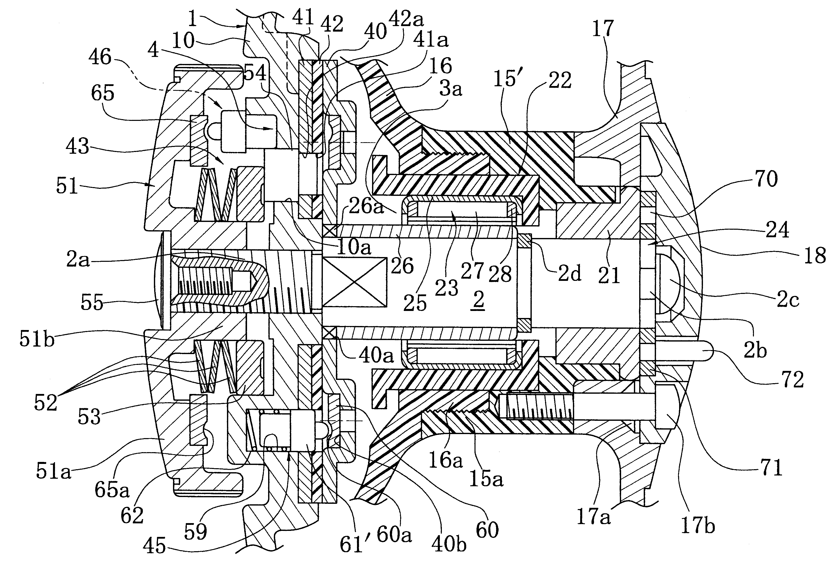
According to the present invention, since the axial length of the guided portion of the guide of the sound producing pin that is guided in the mounting hole is shorter than the length of the portion wherein the sound producing pin and the mounting hole overlap, the length of the guided portion is fixed and the length of the guided portion of the sound producing pin in the mounting hole does not fluctuate no matter how the spacing between the first and second members fluctuates. Consequently, even if the spacing between the first and second members fluctuates, the ease with which the sound producing pin moves does not easily fluctuate, and variation in the quality and volume of the clicking sound can be controlled.According to the present invention, it is possible to construct a spool from a plurality of members facilitating simplified manufacturing and more reliable structural integrity. In addition, since the spool is formed from different members, it is possible to use different materials for each member thereby providing a cost savings and yet the aesthetic appearance can be improved by, for example, making the external flange with a high-grade finish. In addition, a lightweight construction can be achieved by forming portions of a low-cost synthetic resin.

Problems solved by technology

In other words, if the spacing between the two members is narrow, the amount of protrusion of the sound producing pin is small and, consequently, it is difficult for the sound producing pin to move, the sound producing pin scarcely vibrates, the volume diminishes and articulation of the sound is poor.

Method used


Image

  • Single bearing fishing reel and sounding mechanism
  • Single bearing fishing reel and sounding mechanism
  • Single bearing fishing reel and sounding mechanism

Examples


Embodiment Construction

Overall Construction

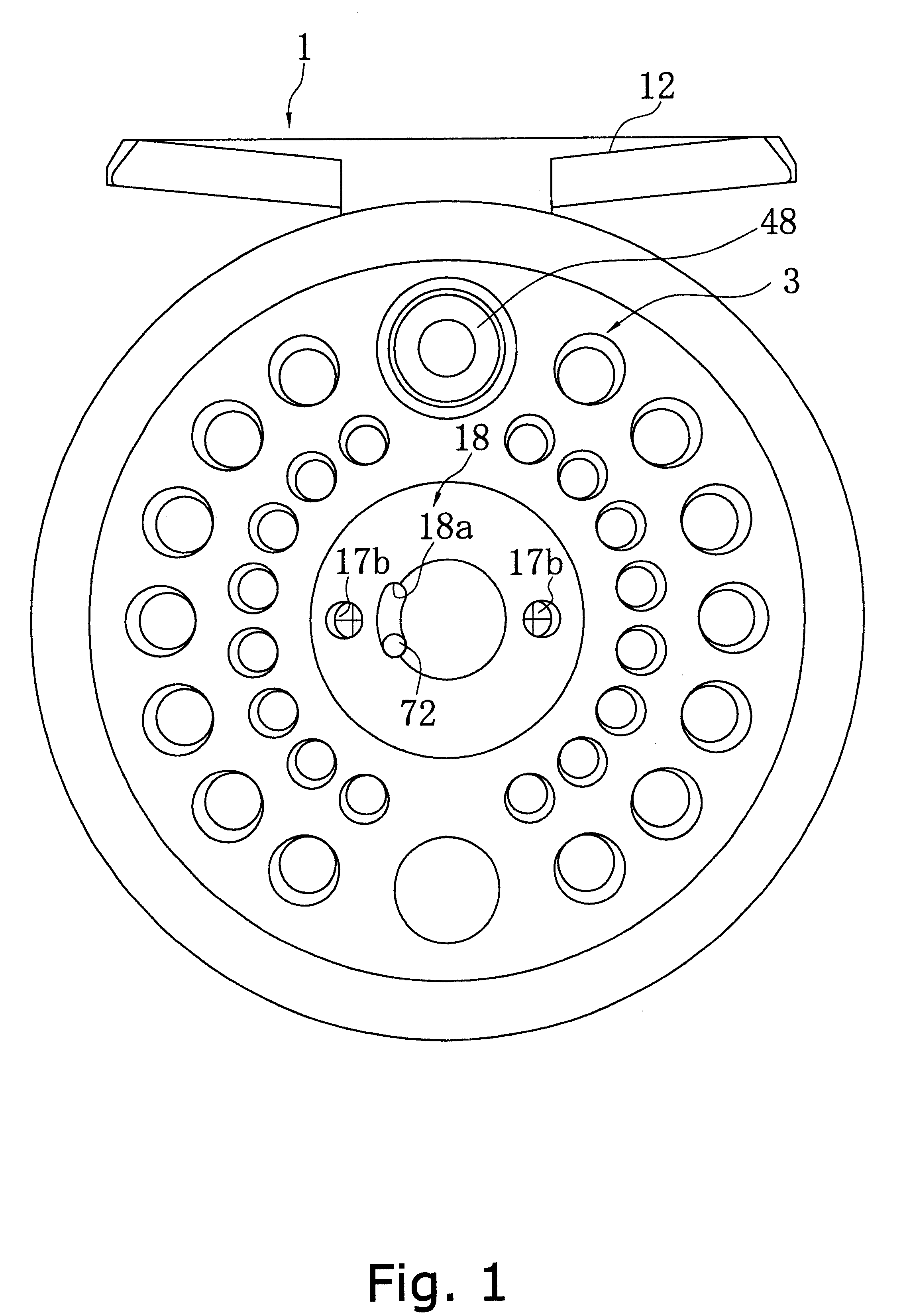
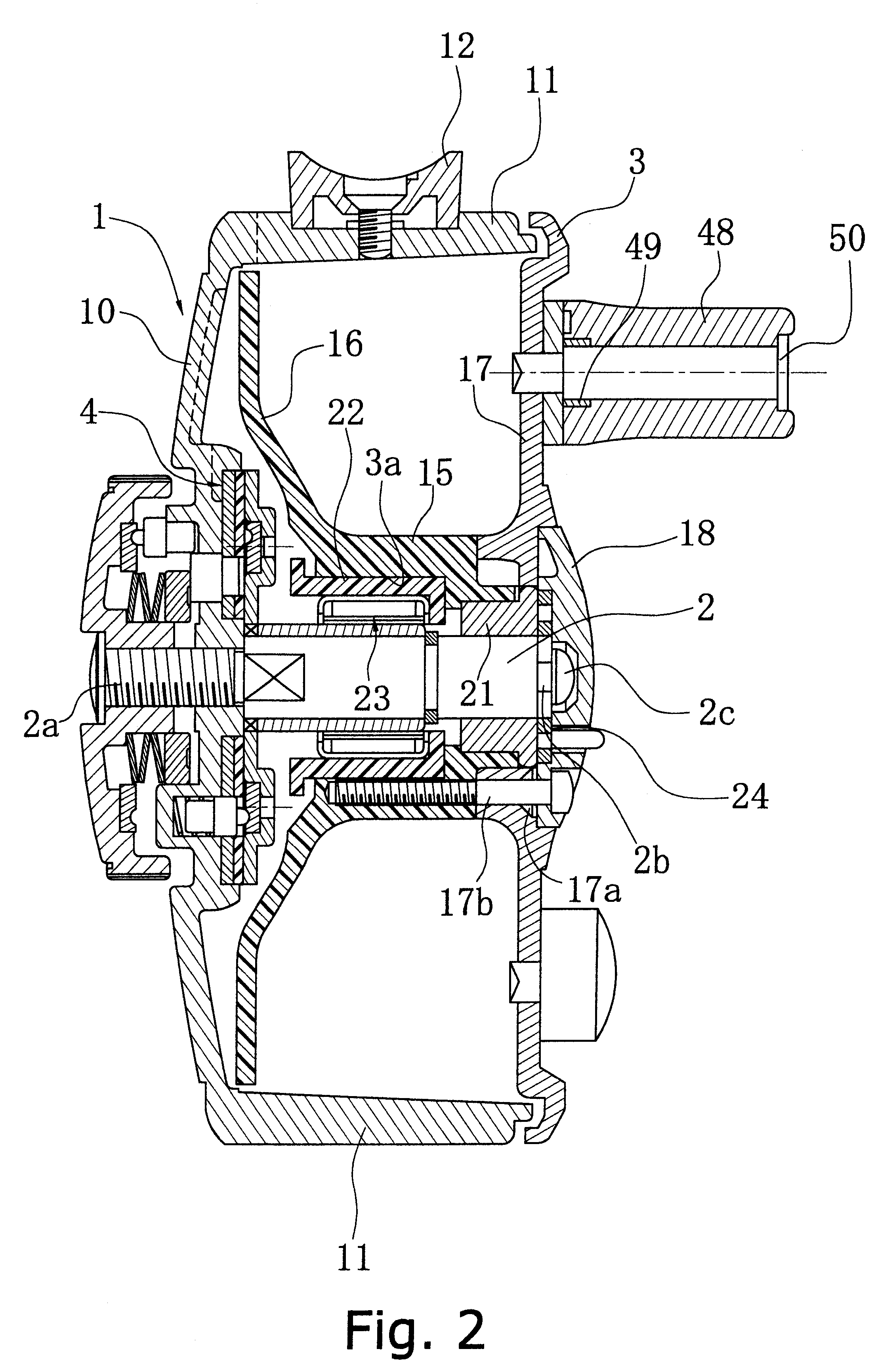
FIG. 1 and FIG. 2 show a single bearing reel according to a first embodiment of the present invention. In FIG. 1 and FIG. 2, the single bearing reel is provided with reel body 1; spool shaft 2 supported within the reel body 1; spool 3 rotatably arranged relative to spool shaft 2 and whereon fishing line is wound around the outer circumference of the spool 3; and drag mechanism 4 that brakes the rotation of the spool 3 in one direction of rotation of the spool 3.

Reel body 1 has disk-shaped side plate 10 on one side (left side of FIG. 2), and is open on a n opposite side thereof. A pair of cover portions 11 (upper and lower) extends in an axial direction from outer peripheral edges of the side plate 10. Although not shown, each of the cover portions 11 extends in a circumferential direction covering at least a portion of the spool 3 leaving at least one open space therebetween for a fishing line to extend out of. The upper side cover portion 11 is provided with mou...


PUM


Abstract

A fishing reel includes a spool that includes a cylindrical spool drum 15, a disk-shaped inner flange 16 mounted on or alternatively formed at one end of the spool drum 15, and outer flange 17 mounted by four bolts 17a to the spool drum 15. Inner flange 16 is formed such that it opposes the side plate of the reel body, and male screw part 16a is provided protruding at the center part thereof. The outer flange 17 is formed by press forming an aluminum alloy, for example.

Description

A. Field Of The InventionThe present invention relates to features of a single bearing fishing reel such as a sounding mechanism within the single bearing fishing reel, where the sounding mechanism is arranged between a first member and a second member of the fishing reel that rotate relative to one another, and the sounding mechanism sounds in response to relative rotation of between the first and second members.B. Description Of The Related ArtA single bearing reel is generally provided with a reel body mounted to a fishing rod; a spool shaft supported cantilevered to the reel body; a spool rotatably mounted about the spool shaft; and a drag mechanism that brakes the spool in one direction.The spool of this type of single bearing reel has a spool drum mounted to the spool shaft and whereon fishing line is wound about the outer circumference; a disk-shaped inner flange mounted on the reel body side of the spool drum; and a disk-shaped outer flange mounted to the other end of the sp...

Claims


Application Information

Patent Timeline
IPC IPC(8): A01K89/016A01K89/00A01K89/01
CPCA01K89/016A01K89/0111A01K89/01931A01K89/0162A01K89/05A01K89/0178
Inventor MORISE, TAISEI
Owner SHIMANO INC
Learn More