Pneumatic tire with sidewall reinforcing rubber and bead reinforcing layer of approximately circumferential cords

a technology of sidewall reinforcement and pneumatic tires, which is applied in the field of pneumatic tires, can solve the problems of increasing tire weight, increasing tire weight, and reducing fuel consumption, so as to prolong the run-flat distance, increase the thickness of reinforcing rubber, and increase the tire weight

Inactive Publication Date: 2002-03-26
BRIDGESTONE CORP
View PDF2 Cites 12 Cited by
  • Summary
  • Abstract
  • Description
  • Claims
  • Application Information

AI Technical Summary

Benefits of technology

In the pneumatic tire according to the invention, the reinforcing rubber mainly disposed at the inside of the sidewall portion while contacting with an inner face of the sidewall portion is contributed to bear the vehicle weight in the puncture of the tire as previously mentioned, whereby the stress concentration into the sidewall portion and the carcass ply can be advantageously prevented in the puncture. In the invention, the cord reinforcing layer of organic fiber cord or steel cord is disposed in at least a bead portion, so that the run-flat running distance can be largely extended under an increase of the weight considerably smaller than the increase of the reinforcing rubber thickness.
That is, the cord reinforcing layer can effectively support the vehicle weight in the puncture of the tire because when the tire is subjected to crushing deformation in the puncture, the vehicle weight in the puncture is supported based on a high tensile strength of the cord in the cord reinforcing layer extending substantially in a circumferential direction against deformation in such a direction that the sidewall portion expands outward in a widthwise direction of the tire, and falling-down of the carcass ply outward in the widthwise direction is effectively restrained under a large crossed angle defined between the cord of the cord reinforcing layer and the cord of the carcass ply in at least the bead portion, and also the cord reinforcing layer functions to obstruct the separation between mutual cords in the carcass ply accompanied with the above expansion deformation of the sidewall portion.
Further, the cord in the cord reinforcing layer is extended in a direction of approximately 90.degree. with respect to a radial line segment and substantially continued in the circumferential direction, so that tension can be advantageously born by such a cord. On the other hand, if the extending angle is not more than 80.degree., the cord bearing tension is discontinued at inner and outer ends in the radial direction, so that the sufficient effect is not developed and the adhesion at the end portion of the cord is insufficient to cause a fear of separation failure.
In the pneumatic tire according to the invention, therefore, the effective extension of the run-flat running distance can be realized by advantageously controlling the expansion deformation of the sidewall portion under the action of the cord reinforcing layer without increasing the thickness of the reinforcing rubber, and also the increase of the tire weight can be controlled to a minimum as far as possible.
In a preferable embodiment of the invention, the cord reinforcing layer has a spirally winding structure of one or more cords. In this case, a joint part is not existent in the cord of the cord reinforcing layer, so that tension is sufficiently born by the cord as mentioned above and the falling deformation of the bead portion can be more effectively restrained. Particularly, when the cord reinforcing layer has a spirally winding structure of plural cords arranged side by side in the radial direction, the formation of the cord reinforcing layer can be facilitated.
In another preferable embodiment of the invention, the cord reinforcing layer is disposed at an outside of the turnup portion of the carcass ply wound around the bead core from the inside toward the outside in the radial direction of the tire. In this case, the formation of the cord reinforcing layer can be more facilitated in connection with the arranging position of the cord reinforcing layer. And also, the cord reinforcing layer is positioned outside a neutral axis, so that it develops a high tensile resistance to the falling deformation of the bead portion and hence the cord reinforcing layer more effectively contributes to support the vehicle weight in the puncture of the tire.

Problems solved by technology

In the conventionally proposed run-flat tires, however, the considerable increase of tire weight is unavoidable for improving the run-flat running performance.
In this case, as the thickness of the reinforcing rubber becomes thicker, the run-flat running distance is extended, but the tire weight is increased to bring about the degradation of fuel consumption, increase of rolling resistance, degradation of ride comfort on the vehicle and degradation of other performances.
On the other hand, if the extending angle is not more than 80.degree., the cord bearing tension is discontinued at inner and outer ends in the radial direction, so that the sufficient effect is not developed and the adhesion at the end portion of the cord is insufficient to cause a fear of separation failure.

Method used


Image

  • Pneumatic tire with sidewall reinforcing rubber and bead reinforcing layer of approximately circumferential cords
  • Pneumatic tire with sidewall reinforcing rubber and bead reinforcing layer of approximately circumferential cords

Examples


Embodiment Construction

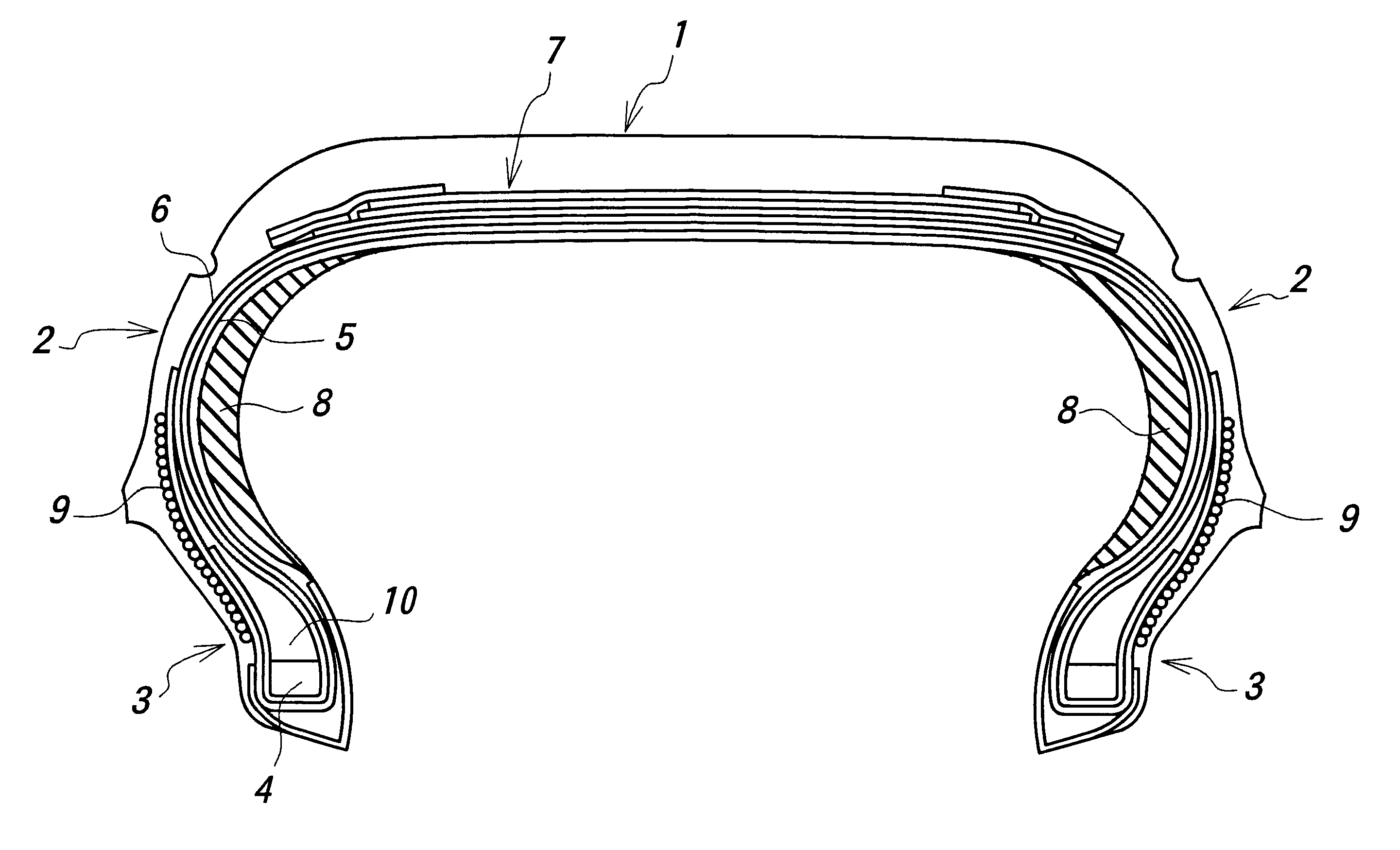
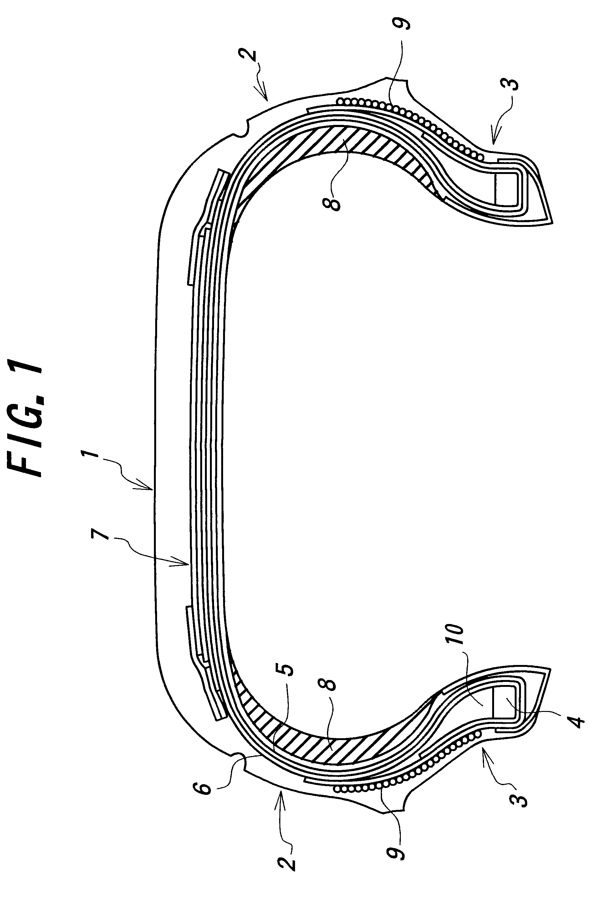
In FIG. 1 is shown an embodiment of the pneumatic radial tire according to the invention, wherein numeral 1 is a tread portion, numeral 2 a sidewall portion connecting to each side end of the tread portion 1 and extending inward in a radial direction of the tire, and numeral 3 a bead portion connecting to an inner peripheral side of the sidewall portion 2.

In this tire, at least one carcass ply, two carcass plies 5, 6 in the illustrated embodiment are toroidally extended between a pair of bead cores 4 embedded in the respective bead portions 3 to reinforce these portions 1, 2 and 3. A side end portion of each carcass ply is wound around the bead core 4 from an inside toward an outside in a widthwise direction of the tire to form a turnup portion. And also, a belt 7 comprised of at least one belt layer is arranged on an outer periphery of a crown portion of the carcass ply.

Moreover, each of the carcass plies 5, 6 contains cords arranged substantially in the radial direction therein.

Fu...


PUM


Abstract

A pneumatic tire comprises a tread portion, a pair of sidewall portions, a pair of bead portions, and at least one carcass ply toroidally extending between a pair of bead cores and wound around the bead core to form a turnup portion, in which a reinforcing rubber having substantially a crescent shape at its lateral section is disposed at an inside of the sidewall portion and a cord reinforcing layer containing cord(s) extending in a direction of approximately 90° with respect to a radial line segment is disposed in at least a bead portion.

Description

1. Field of the InventionThis invention relates to a pneumatic tire, and more particularly to an improvement of a run-flat tire wherein a runnable distance in the puncture of the tire or so-called run-flat running distance can largely be extended while controlling the increase of tire weight.2. Description of Related ArtAs the run-flat tire capable of temporarily running in the puncture of the tire, there have hitherto been proposed tires of various types, a part of which has already been commercialized.In the conventionally proposed run-flat tires, however, the considerable increase of tire weight is unavoidable for improving the run-flat running performance. Particularly, there is a case that the tire weight is increased by about 30%.For example, there is a run-flat tire having such a type that a reinforcing rubber having substantially a crescent shape at its lateral section is disposed at an inside of a sidewall portion of the tire and contributed to bear a weight of a vehicle bo...

Claims


Application Information

Patent Timeline
Patent Type & Authority Patents(United States)
IPC IPC(8): B60C17/00B60C15/06B60C13/00
CPCB60C15/06B60C17/0009Y10T152/10828Y10T152/10864
Inventor IWASAKI, SHIZUO
Owner BRIDGESTONE CORP
Why Eureka
Try Eureka