Apparatus for a quick release mechanism in a railcar hand brake

Inactive Publication Date: 2002-04-02
WESTINGHOUSE AIR BRAKE TECH CORP
View PDF6 Cites 28 Cited by
  • Summary
  • Abstract
  • Description
  • Claims
  • Application Information

AI Technical Summary

Benefits of technology

Another object of the present invention is to increase railcar wheel life by reducing the premature wear between the railcar brakes and the wheels as a result of friction between the brakes and the wheels due to unintentional brake application during train operation.
Still a further object of the present invention is to increase railway track life by reducing the friction between the wheels and the track

Problems solved by technology

However, the brake may not be fully released.
Friction and wear between the b

Method used


Image

  • Apparatus for a quick release mechanism in a railcar hand brake
  • Apparatus for a quick release mechanism in a railcar hand brake
  • Apparatus for a quick release mechanism in a railcar hand brake

Examples


Embodiment Construction

Prior to preceding to a more detailed description of the invention, it should be noted that identical components having identical functions have been designated with identical reference numerals for the sake of clarity.

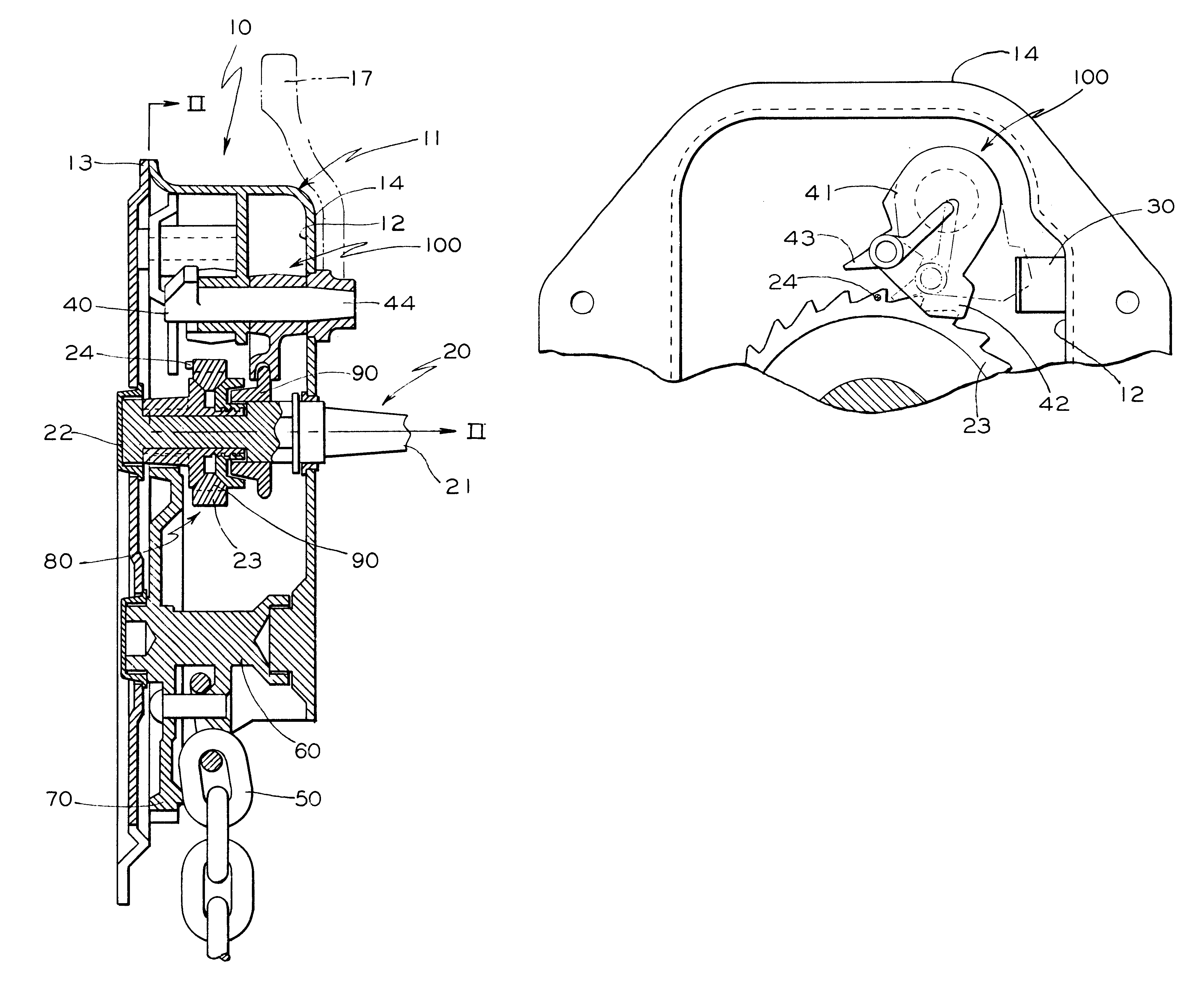
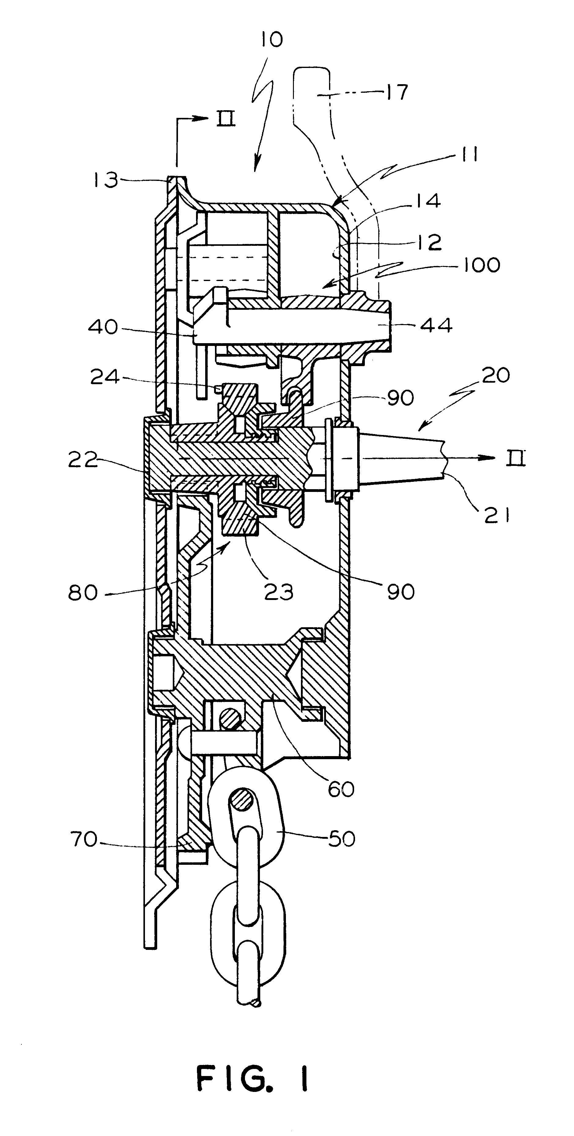
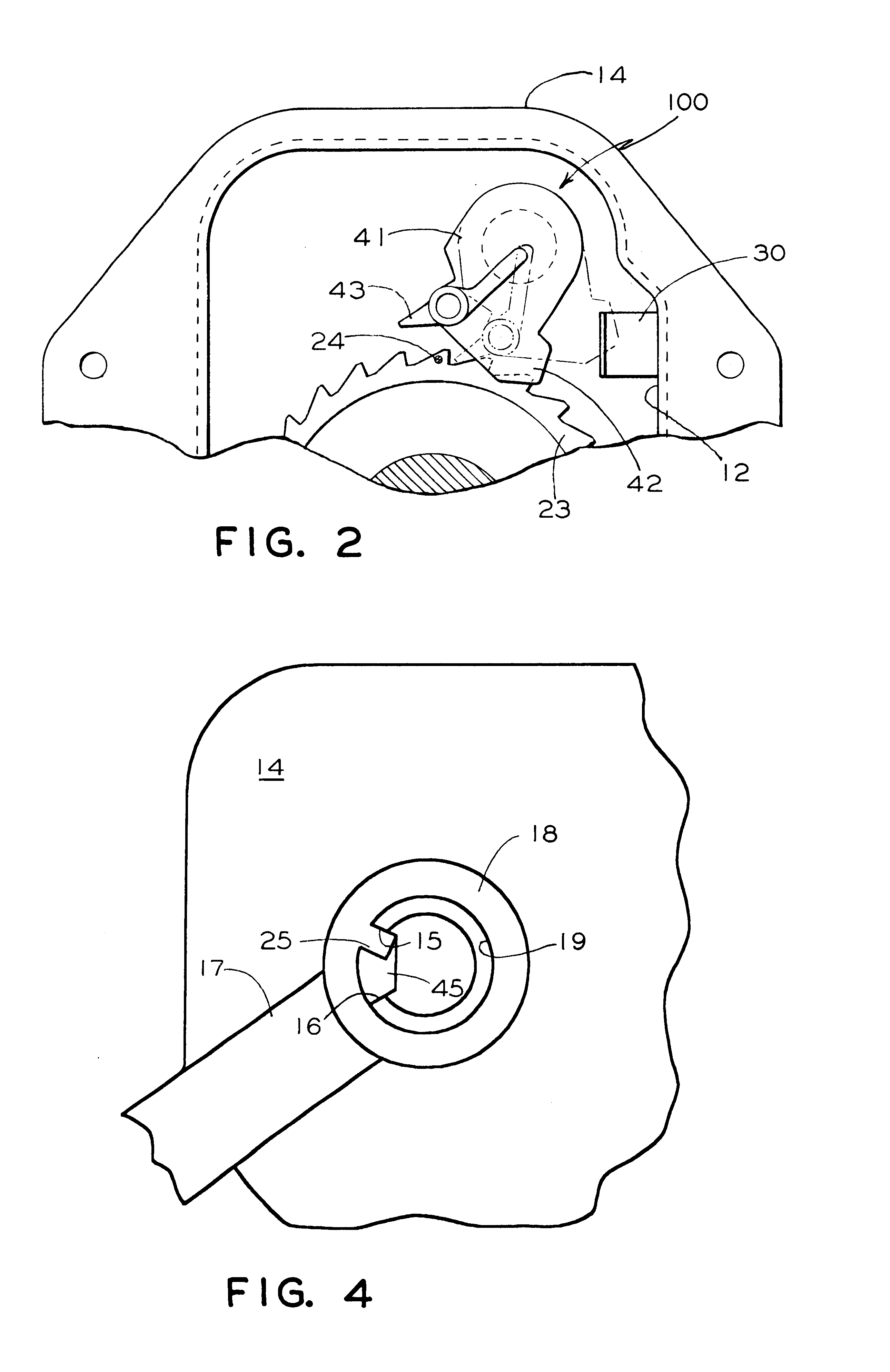
Now refer more particularly to FIGS. 12, and 3 of the drawings. Illustrated therein is an apparatus for a quick release mechanism in a railcar hand brake. The railcar hand brake, generally designated 10, has a housing, generally designated 11. The housing comprises a front casing 14 including an inside wall 12 of a predetermined size and shape, and a back plate 13. An operating shaft, generally designated 20 is rotatably mounted in the housing 11. The operating shaft 20 includes a first end 21 and a second end 22. A ratchet wheel 23 is rotatable with the operating shaft 20 and intermediate the first end 21 and second end 22. A release shaft 40 is rotatably mounted in the housing 11.

The apparatus comprises a projection 24 of a predetermined size and shape disposed subs...


PUM


Abstract

An apparatus for a quick release mechanism in a railcar hand brake. The hand brake has a housing having a front casing with an inside wall of a predetermined size and shape, and a back plate. An operating shaft is rotatably mounted in the housing. The operating shaft includes a first end and a second end. The operating shaft further includes a ratchet wheel rotatable with the operating shaft intermediate the first and second ends thereof, and a release shaft rotatably mounted in the housing. The apparatus comprises a projection of a predetermined size and shape disposed substantially perpendicular to the ratchet wheel, and a flexible clamp of a predetermined size and shape mounted inside the housing. A member is disposed substantially perpendicular to, and about the circumference of the release shaft, having a first element disposed on the member wherein the first element interposes with the flexible clamp when the release shaft is rotated to achieve and maintain full brake release, and a second element disposed on the member and engageable with the projection when the operating shaft is rotated to disengage the first element from the flexible clamp to allow for brake application.

Description

The present invention relates, in general, to a railcar hand brake, and more particularly, to an apparatus for a quick release mechanism in a railcar vertical wheel hand brake. The present invention will maintain a hand brake in the released position until an application is made.Prior to the present invention, a railcar vertical hand brake includes a brake release mechanism that provides quick release of the brakes by disengaging the winding gear to permit free rotation of the main gear wheel. A force is exerted on the release lever to move the attached brake release shaft, whereby releasing the main gear wheel and the tension on the brake chain, which in turn releases the brake. When the force on the release lever is removed, the main gear wheel re-engages. However, the brake may not be fully released. When a railcar negotiates a curve in the track, the truck rotates and can exert a force on the brake chain. The chain resists the truck movement and tends to pull on the hand brake l...

Claims


Application Information

Patent Timeline
IPC IPC(8): B61H13/04B61H13/00B60T7/10
CPCB61H13/04Y10T74/20612Y10T74/20642Y10T74/2048
Inventor LABRIOLA, ANGELO M.RING, EVERETT G.
Owner WESTINGHOUSE AIR BRAKE TECH CORP
Why Eureka
Try Eureka