
Arrangement for dosing pourable substances and associated uses

a pourable substance and pourable technology, applied in the direction of special packaging, liquid bottling, packaging goods, etc., can solve the problems of affecting the use of the pourable substance, the content of the powder flask to explode, and the inability to directly load the muzzleloader weapon, etc., to achieve the effect of convenient transportation

Inactive Publication Date: 2002-04-09
HOERMANN KARL LUDWIG HARAL
View PDF4 Cites 7 Cited by
  • Summary
  • Abstract
  • Description
  • Claims
  • Application Information

AI Technical Summary

Benefits of technology

The general object of the present invention consists in overcoming the disadvantages occurring in the prior art and to provide an applicable, flexible and easily transportable arrangement as well as to determine uses by which amounts of

Problems solved by technology

Particularly with propellants such as black powder or that like, a hazard exists, that, after the shot, glowing residuals adhering to the muzzle of the weapon, while leading up the storage container, for example a classical powder flask or a powder horn with a measuring socket attached to it, to the muzzle of the weapon, igniting the powder contained therein and thus brings the content of the powder flask to blast.
Since the powder flask is at this moment close to the upper body and the face, such an incident leads to grave and possibly lethal injuries of the user and persons surrounding him.
Therefore, in many countries it is no longer permissible to load a muzzleloader weapon directly from the powder flask.
Besides, there is a latent hazard that powder gets spilled.
Especially on closed shooting ranges the hazard exists that residuals mix with the remains of spilled black powder.
Furthermore, this deflagration may bring to reaction other propellants or explosives held in containers in the rooms.
It is disadvantageous that the tubes are in close proximity of the supply container.
The known powder-filling device did not meet wide acceptance.
However, this is not permissible in closed shooting-ranges, since the stripped powder falls onto the ground and is only removable by difficulty from gaps.
In addition, powder is wasted.
However, this has the great disadvantage, particularly when firing with muzzleloaders, that the storage container is often not closed from lack of time after removing the desired quantity.
This can lead to a serious explosion of the powder contained in the storage container.
While firing, a problem often occurs with regard to the hit point respectively the reach.
Because of the slowed-down ignition front the yield of powder converted into gas drops, resulting in the described loss of performance.
Since a change of the charge on site in closed rooms is not possible on account of the conditions described earlier, the users compensate the loss of performance by changing the aiming point according to `feel` more or less successfully.
After twist of the dispenser, the content of the measuring chamber can leak while opening the cover.
The clearing also presents a problem since residuals remain easily in the storage container.
However, it turned out that the required accuracy is, in practice, hardly achievable as the filling status of the storage space is contrary to expectations a subject of high variations.
Moreover, gunpowder tends to clotting.
However, this is only suitable for stationery application.
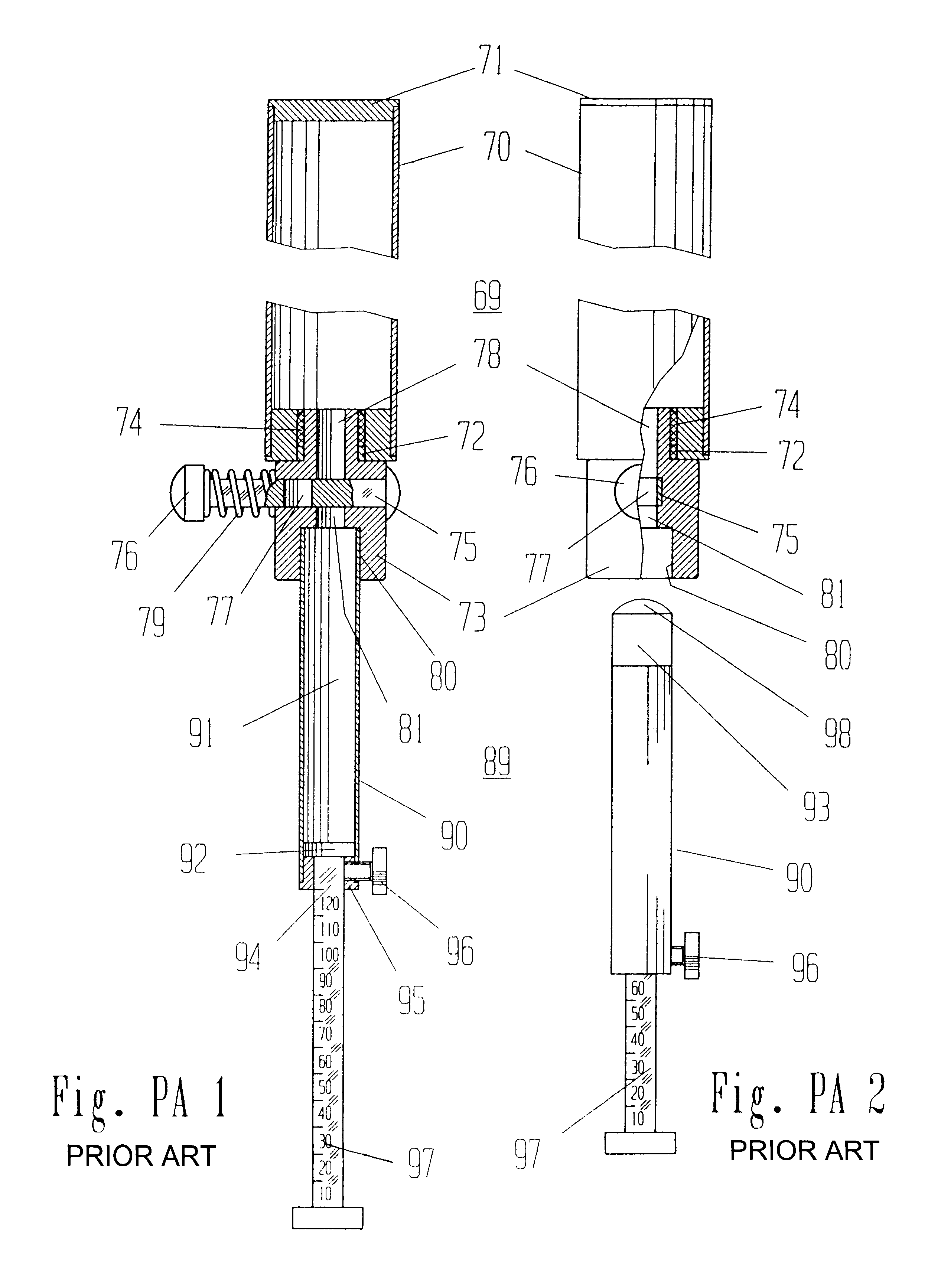
Firstly, it is a disadvantage that the powder charge produced in such way is relatively inaccurate.
Furthermore, the storage container 69 may not be emptied completely when changing from black powder to nitrocellulose powder.
Finally, the association of the dosing unit to the closure may easily become disturbed during handling, which leads, in the least case, to an inaccurate amount of powder, and in the worst case to an unintentional release of powder.
Furthermore, the clotting of substance leads to an incomplete filling of the measuring chamber 91.

Method used


Image

  • Arrangement for dosing pourable substances and associated uses
  • Arrangement for dosing pourable substances and associated uses
  • Arrangement for dosing pourable substances and associated uses

Examples


example 2

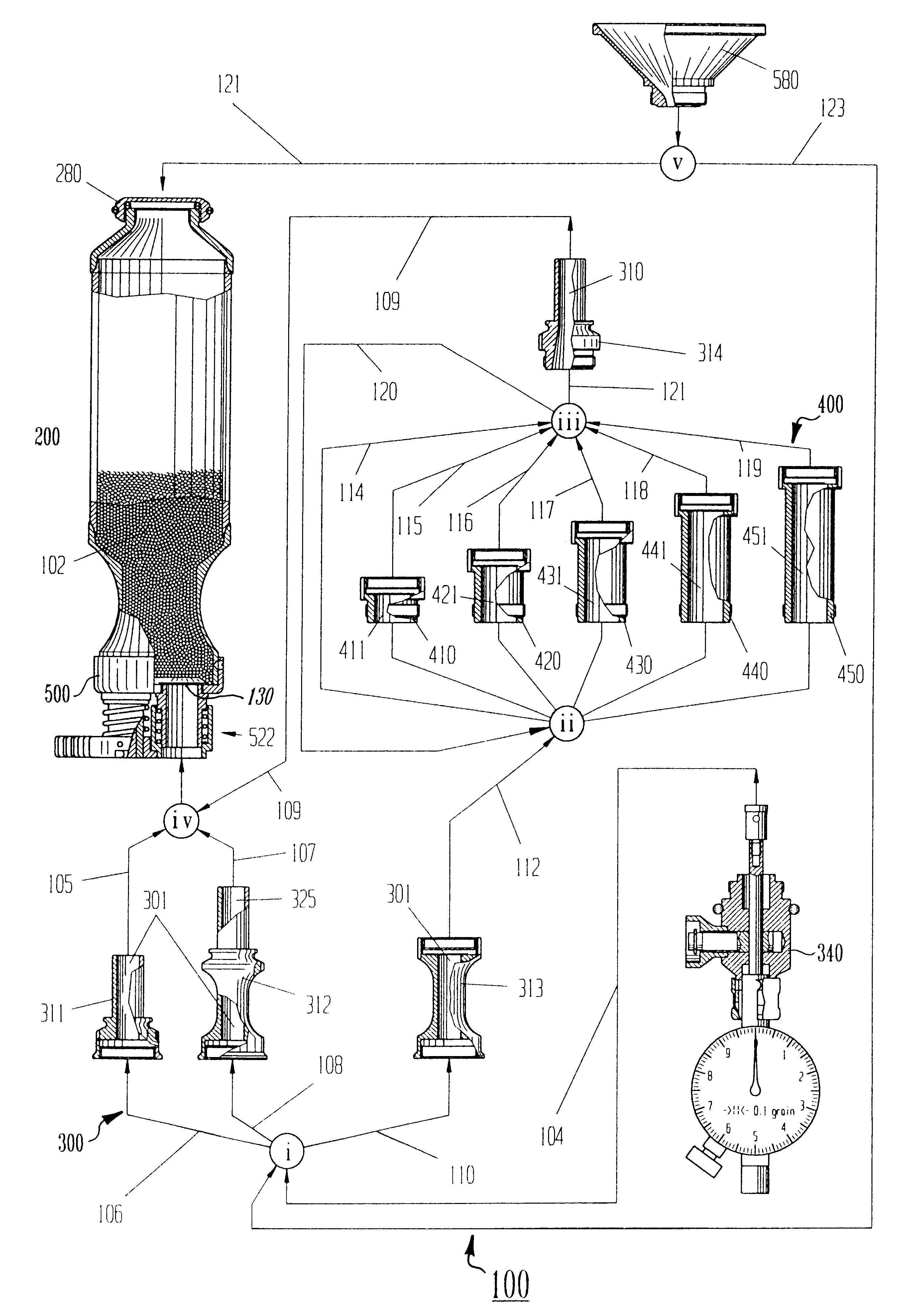
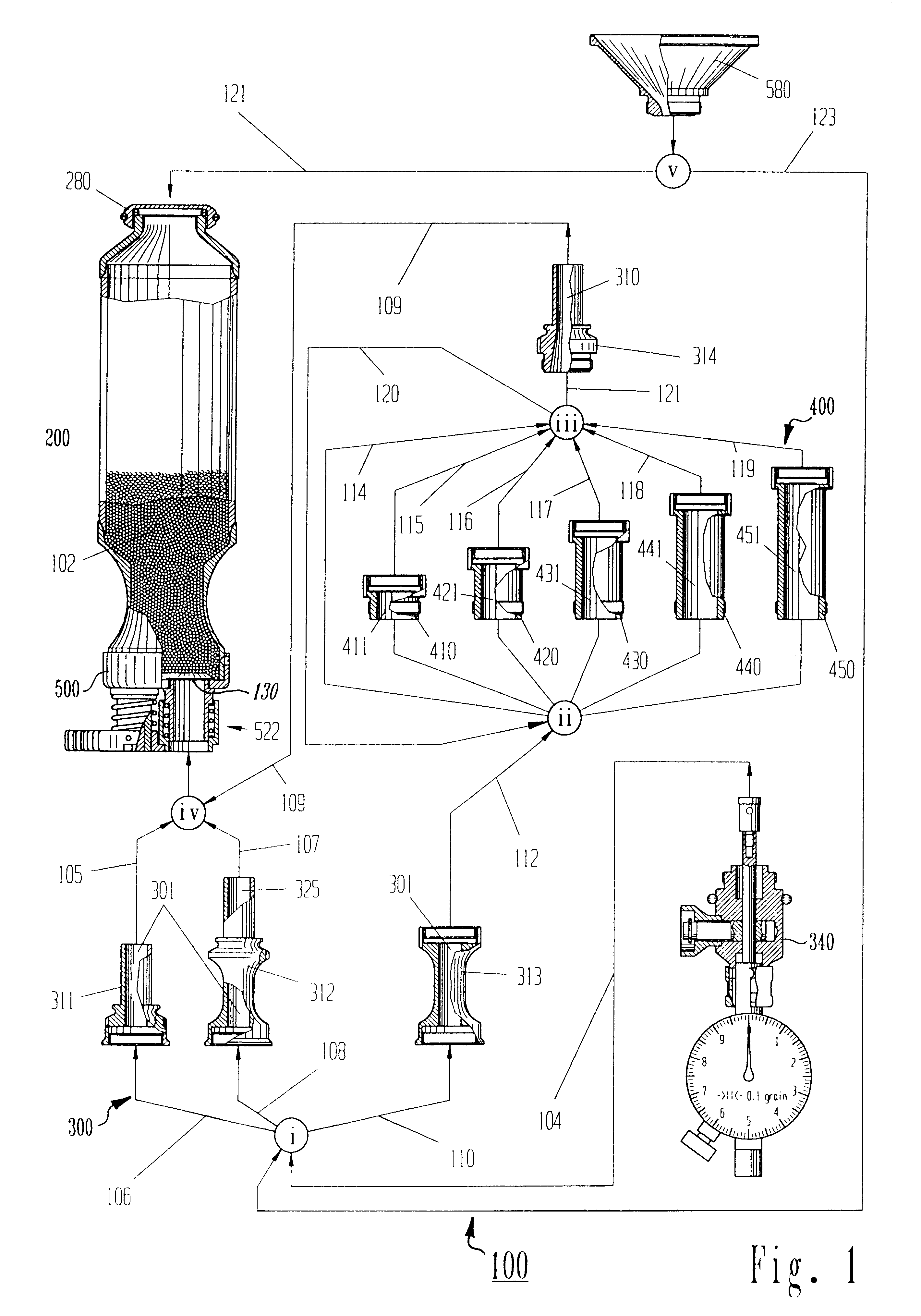
If SM 17.0 grain is desired as a nominal quantity, thus according to (2) follows for TM=10 grain and according to (3) for RM=7.0 grain. This is still within the range of the large measuring part 312 being associable to the measure carrier 340 via the connecting path 108, since the entire volume of the large measuring part 312 consists of the measuring chamber 301 containing maximum of 10.0 grain and of the measuring cavity 325 representing one effective volume WV of 10.0 grain and the large measuring part 312 thus contains up a maximum of 20 grain.

example 3

Assuming as nominal quantity SM 27.0 grain, (2) leads to TM=20 grain and (3) to RM=7 grain. The nominal quantity SM is now larger than the volume capacity of the measuring parts 311 or 312. In this case, there is via the connecting path 110 to the measure carrier 340 the base part 313 associable, to which the bung piece 314 is associable via the connecting path 112 to the logic node and directly via the connecting path 114 to the logic node iii via the connecting path 121, and the residual quantity RM in the amount of 7.0 grain is again adjustable via the measuring chamber 301.

example 4

Assuming a nominal quantity of SM 96.5 grain, from (2) follows for TM=90 grain and from (3) for RM=6.5 grain. FIG. 5A and FIG. 5B show a block diagram for determination of the combination of measuring-bodies, depending on the partial quantity TM and on the residual quantity RM. In the case the maximum volume capacity is exceeded or if SM<0.0, a fault report occurs. After initialization of the input data, namely of the bung socket's cavity 310 (SPK), the number of sockets (NMAX), a vector STUKAP (NMAX) with the capacities of the sockets in descending order and the specification of the effective volume WV, the partial quantity TM and the residual quantity RM are determined according to equations (2) and (3). If the partial quantity TM is larger or equal 0, an effective volume 320 (WV) is subtracted from the partial quantity TM. In case the partial quantity TM is larger or equal to the measuring cavity 310 of the bung piece 314 (SPK), this (SPK) is subtracted from the partial quantity ...


PUM

PropertyMeasurementUnit
Massaaaaaaaaaa
Massaaaaaaaaaa
Massaaaaaaaaaa

Abstract

Arrangement for dosing granular materials, propellants, explosives, gunpowder and other pourable substances comprising at least a container with a closure and a dosing unit comprising a measuring chamber for the take up of said substance, said dosing unit is defined connectable with the container via a means of association for the purpose of dosing, whereby said closure is held self-powered in a closed position and is transferable by a means of actuating into an open position for opening. At least one means of locking is provided securing the closure in the closed position in order to prevent unintentional release of substance, whereby the means of locking is releasable preferentially by the dosing unit while connecting with the container latest while attaining the filling location in order to rest the closure in the closed position as possible long and effect an constrained control. For additional security at least one means of holding my be provided in order to rest the association of dosing unit and container in the filling position. Said arrangement comprising a container for taking up of the substances, which is utilizing an active generation of a throttle effect by means of a field of lateral force. The container may be equipped with a funnel-shaped section being closable by means of a lid for the easier clearing of the container. Said arrangement further comprises a preferred clamping holder for taking up the container and a preferred holding device comprising a means of pressure equalization; furthermore preferred uses of the dosing unit and the arrangement and a preferred adhesive-joint for the container increasing the stability under load, particularly at swelling loads as well as three-dimensional stress condition. And finally a preferred tenter tool preventing the dosing unit from damages while assembling it.

Description

1. Field of InventionThe invention relates to an arrangement for dosing granular materials, propellants, explosives, gunpowder and other pourable substances comprising at least a dosing unit with a measuring chamber for the taking up at least one effective volume of such a substance and a container for the substance with a closure, being transferable from a closed position into an open position, as well as an adhesive-joint to join the components of the container, a clamping holder to carry the container and a holding device for the vertical holding of the container attached at the clamping holder.Furthermore, the invention concerns a preferred use for the adjustment of a desired nominal quantity SM of the substance on the dosing unit, as well as preferred uses of the device for the arrangement for dosing such substances by utilization of gravity.In as much as in the following it is spoken about charge, thereby is generally meant an amount of such a substance. The term powder is use...

Claims


Application Information

Patent Timeline
IPC IPC(8): C06B21/00F42B33/00F42B33/02
CPCF42B33/0292C06B21/00
Inventor HOERMANN, KARL LUDWIG HARAL
Owner HOERMANN KARL LUDWIG HARAL
Learn More