Self-feeding soldering device

a soldering device and self-feeding technology, applied in the direction of ohmic-resistance heating, soldering apparatus, manufacturing tools, etc., can solve the problem of holding the two elements

Inactive Publication Date: 2002-04-09
MORRISON TERRY H
View PDF16 Cites 35 Cited by
  • Summary
  • Abstract
  • Description
  • Claims
  • Application Information

AI Technical Summary

Problems solved by technology

Although once this is accomplished the solder joint is effective, it can be difficult, when in cramped conditions, to hold the two elements together while simultaneously heating them with a soldering device and then rapidly feeding the solder wire onto the elements while they are still hot enough to melt the solder.

Method used


Image

  • Self-feeding soldering device
  • Self-feeding soldering device
  • Self-feeding soldering device

Examples


Embodiment Construction

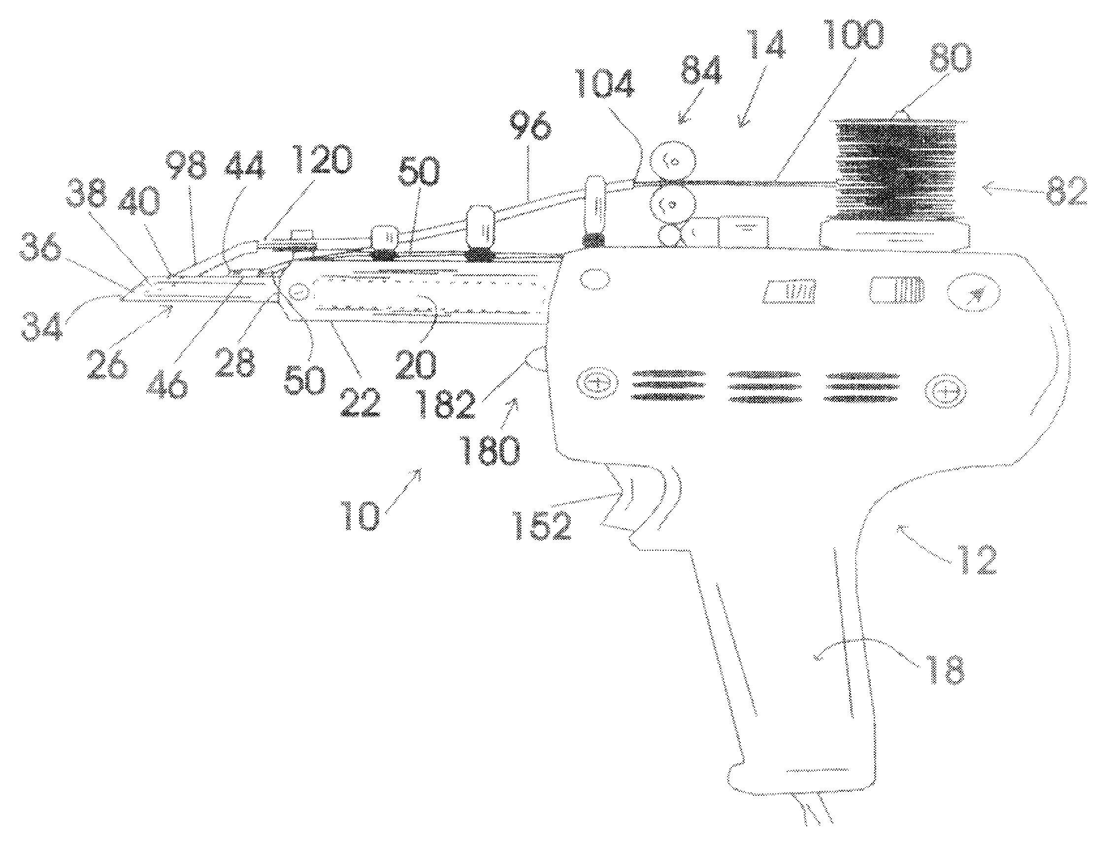
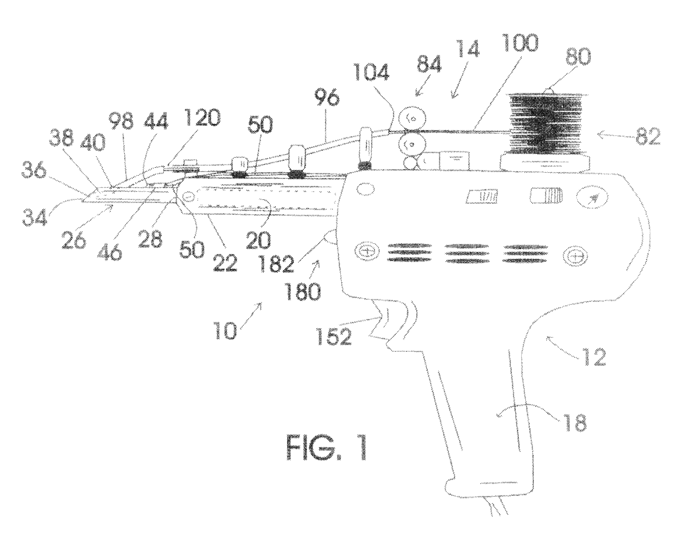
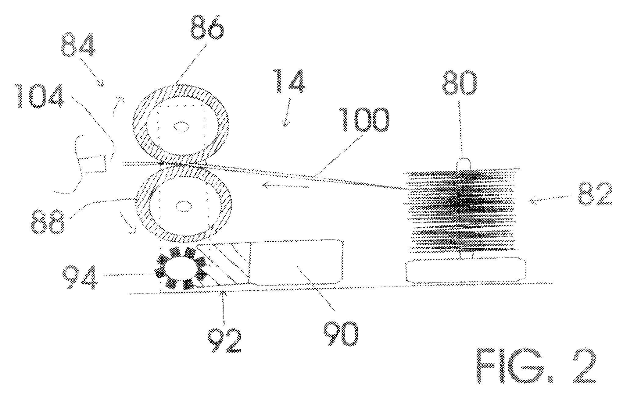
FIGS. 1-6 various exemplary embodiment of the self-feeding soldering device of the present invention generally designated 10. Self-feeding soldering device 10 includes a soldering assembly, in the embodiment a solder gun assembly, generally designated 12; a solder feed mechanism, generally designated 14, carried on the soldering assembly 12; and a solder system controller, generally designated 16, in controlling connection with soldering assembly 12 and solder feed mechanism 14.

Solder gun assembly 12 includes: a molded plastic pistol grip housing, generally designated 18; an electrical resistance cartridge heater element 20 (shown in dashed lines) housed within a high heat conductivity barrel 22 supported by the pistol grip housing 18; a detachable soldering tip, generally designated 26, having a barrel connecting end 28 detachably connectable to an end 30 of high heat conductivity barrel 22 with a set screw 32; a solder dispensing surface 34 having a solder dispensing opening 36 in...


PUM


Abstract

A self feeding soldering device includes a soldering device; a solder feed mechanism carried on the soldering device; and a solder system controller in controlling connection with the soldering device and the solder feed mechanism. The solder feed mechanism allows the user to control the feed of solder wire onto the heated soldering tip of the soldering device or the area adjacent to the heated soldering tip to be soldered to free one hand of the user to secure the objects to be soldered.

Description

The present invention relates to soldering equipment and more particularly to a self-feeding soldering device including a soldering assembly, a solder feed mechanism carried on the soldering assembly, and a solder system controller in controlling connection with the soldering assembly and the solder feed mechanism; the soldering assembly including: a pistol grip housing, an electrical resistance cartridge heater element housed within a high heat conductivity barrel supported by the pistol grip housing, a detachable soldering tip having a barrel connecting end detachably connectable to an end of the high heat conductivity barrel, a solder dispensing surface having a solder dispensing opening in connection with a solder passageway formed through the soldering tip between a soldering tip solder insertion side opening and solder dispensing opening, a tip temperature sensor having a temperature sensing transducer mechanically connected to the soldering tip and having an insulated transdu...

Claims


Application Information

Patent Timeline
Patent Type & Authority Patents(United States)
IPC IPC(8): B23K3/06
CPCB23K3/0615
Inventor MORRISON, TERRY H.
Owner MORRISON TERRY H
Why Eureka
Try Eureka