
Circuit and method for detecting backward spin of a spindle motor for a disk drive

Inactive Publication Date: 2002-04-09
STMICROELECTRONICS SRL
View PDF22 Cites 28 Cited by
  • Summary
  • Abstract
  • Description
  • Claims
  • Application Information

AI Technical Summary

Problems solved by technology

One problem encountered in driving and / or controlling a synchronous motor in a disk drive system is the disk initially spinning in a reverse direction relative to an operative forward direction.
When a sequence of drive signals are applied to the motor windings during a spin up routine, the initial timing of the sequence of applied drive signals may potentially be incorrect relative to the position of the motor's rotor, thereby generating negative torque and causing the disk to undesirably spin in a direction that is opposite of the direction of spin during normal operation.
This condition is further complicated by the fact that oftentimes different motors and power supplies are used in disk drive systems, thereby presenting additional variables to driving the disk motor which may lead to greater uncertainty in avoiding negative torque and backward disk spin.

Method used


Image

  • Circuit and method for detecting backward spin of a spindle motor for a disk drive
  • Circuit and method for detecting backward spin of a spindle motor for a disk drive
  • Circuit and method for detecting backward spin of a spindle motor for a disk drive

Examples


Embodiment Construction

The present invention will now be described more fully hereinafter with reference to the accompanying drawings in which a preferred embodiment of the invention is shown.

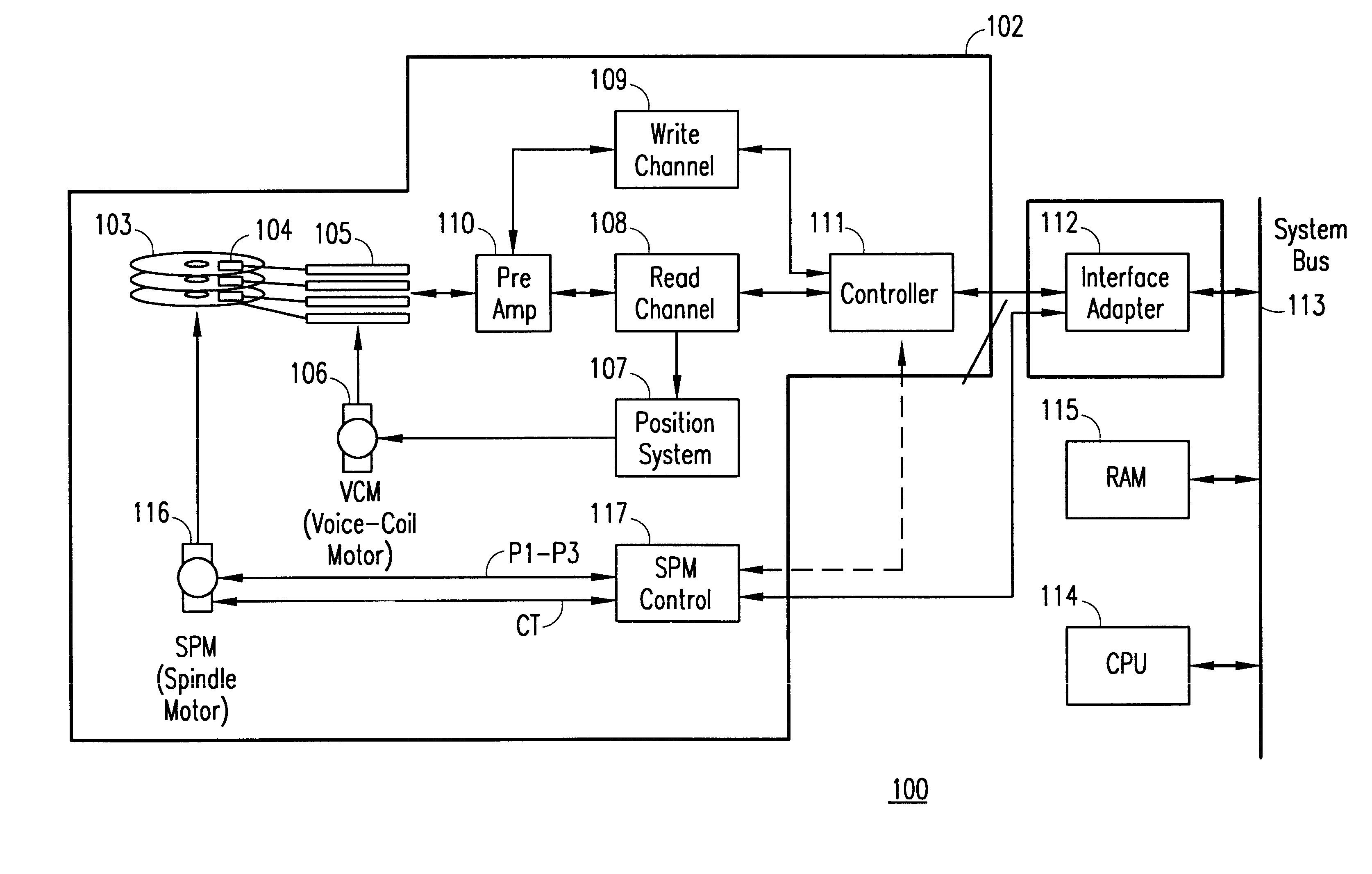
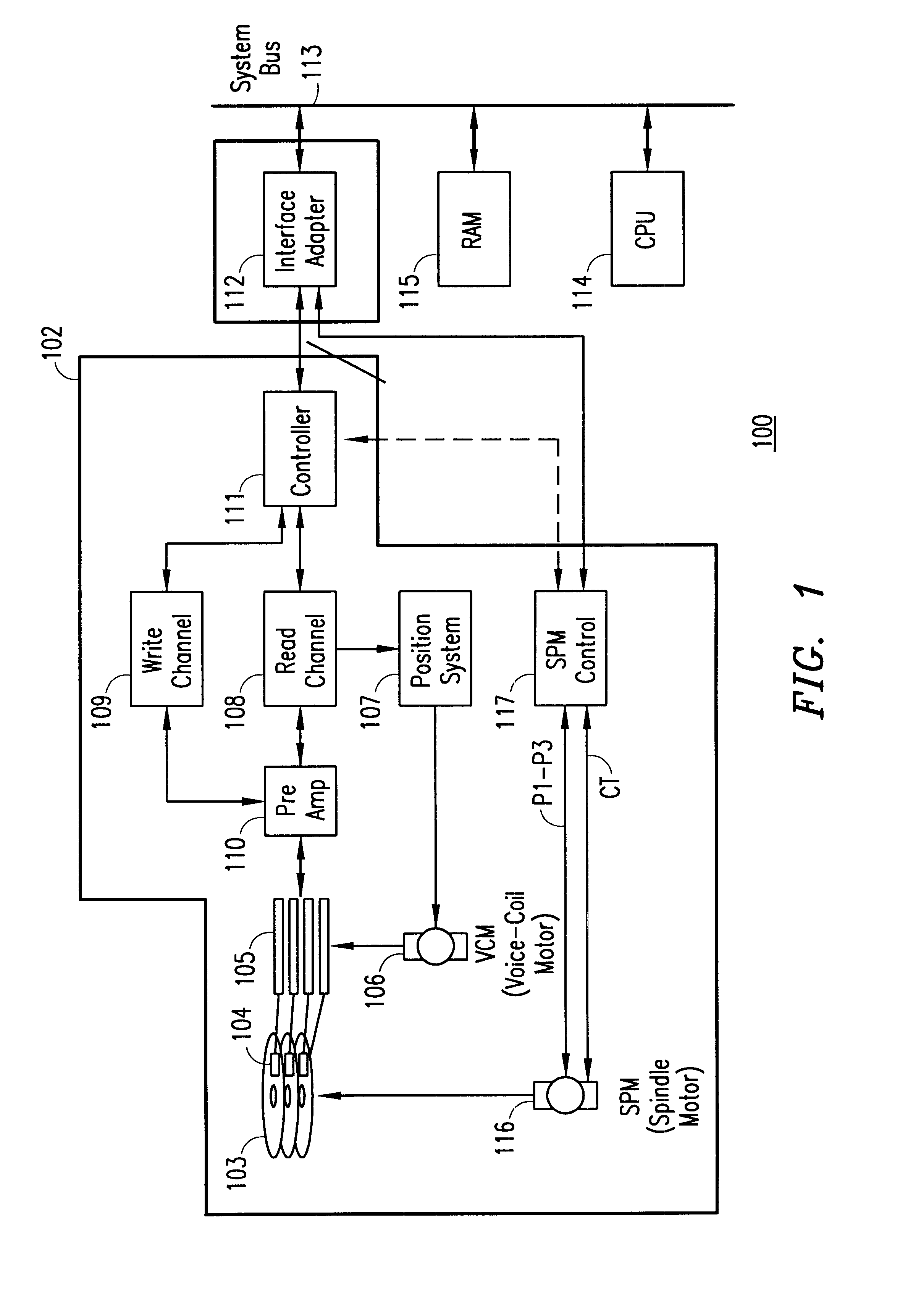
Referring to FIG. 1, there s shown a block diagram of an exemplary disk drive system 100 including a disk drive 102 in accordance with the present invention. Disk drive 102 includes a storage medium in the form of ore of more disks 103, each of which may contain data on both sides of the disk. Data is written to disks 103 and / or read therefrom by one or more read / write heads 104. The read / write head 104 is connected to an arm 105, with both read / write head 104 and arm 105 being positionally controlled by a voice-coil motor ("VCM") 106 and a position system 107. The position system 107, through VCM 106, positionally maintains and / or moves head 104 radially over the desired data on disks 103. A read channel 108 converts an analog read signal from head 104 into digital form. A write channel 109 provides data in analog f...


PUM


Abstract

A circuit and method are disclosed for determining whether a brushless polyphase motor is spinning in a reverse direction relative to spin direction during normal operation. The circuit receives a back emf signal of a first phase line and determines a polarity of the back emf signal following a back emf signal associated with a second phase line crossing a zero reference level. Based upon the determined polarity of the back emf signal of the first phase line, the circuit selectively asserts an output signal indicating that the motor is spinning in the reverse direction.

Description

1. Technical Field of the InventionThe present invention relates to controlling brushless motors, and particularly to a circuit and method for detecting a backward spin of a polyphase motor for use in the control thereof.2. Background of the InventionA "brushless" motor includes a permanent magnet rotor and a stator made up of a number of windings that may be connected in a star configuration or completely independent from each other. In the first case there exist a number of external terminals equal to the number of the motor's phases. In the second case reference is made to motors with independent phases and both terminals of each winding being available externally. These motors are commonly used in hard and floppy disk drives, DVD (digital video disk) drives, tape video recorders, CD players, etc.In the majority of cases, brushless motors are three-phase and the driving circuit generally comprises integrated circuits whose output stages drive the phase windings or lines. The inte...

Claims


Application Information

Patent Timeline
IPC IPC(8): G11B19/28H02P6/00H02P6/22H02P6/16H02P6/18
CPCH02P6/22G11B19/28
Inventor MENEGOLI, PAOLO
Owner STMICROELECTRONICS SRL
Features
  • Generate Ideas
  • Intellectual Property
  • Life Sciences
  • Materials
  • Tech Scout
  • Unparalleled Data Quality
  • Higher Quality Content
  • 60% Fewer Hallucinations
Learn More