Display arrangements

a display and display technology, applied in the field of display arrangements, can solve the problems of large design effort, relatively large and unwieldy umbilical cords, and generally quite complex relay optics

Inactive Publication Date: 2002-04-09
BAE SYSTEMS PLC
View PDF34 Cites 20 Cited by
  • Summary
  • Abstract
  • Description
  • Claims
  • Application Information

AI Technical Summary

Problems solved by technology

The relay optics are generally quite complex, involving several elements for focussing and directing the image, and require a significant degree of design effort to integrate them with the CRT and with the part of the system which the pilot actually views.
It also requires a relatively large and unwieldy umbilical cable to provide the electrical supply to the CRT.
This leads to difficulties in adequately shielding the long run of cable to prevent electromagnetic interference effects.
The size and weight of the umbilical may also inhibit the pilot's head movements and can be particularly problematical where the aircraft is expected to undergo maneuvers involving high gravitational forces.
In normal helmet-mounted displays using CRTs, monochrome only is available because the shadow mask required for color cannot be accommodated in the small space available and also vibration can be a problem.
Furthermore, a very bright display is required and this is difficult to achieve in small color CRT displays.

Method used


Image

  • Display arrangements
  • Display arrangements

Examples


Embodiment Construction

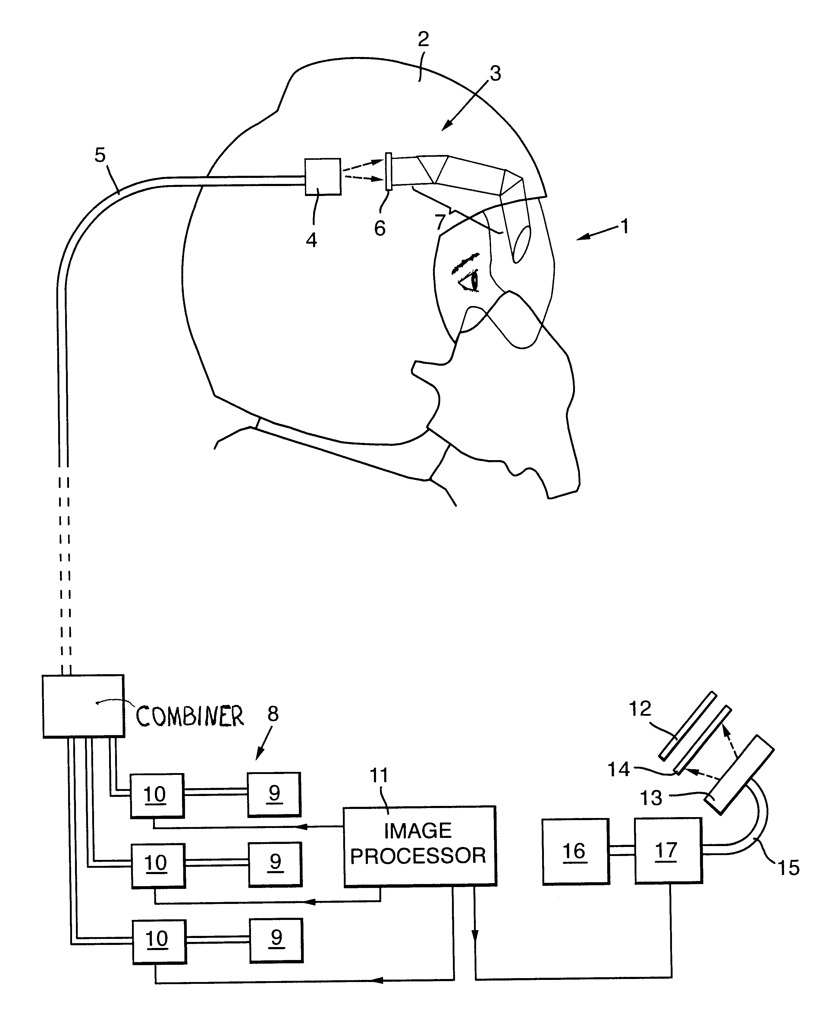
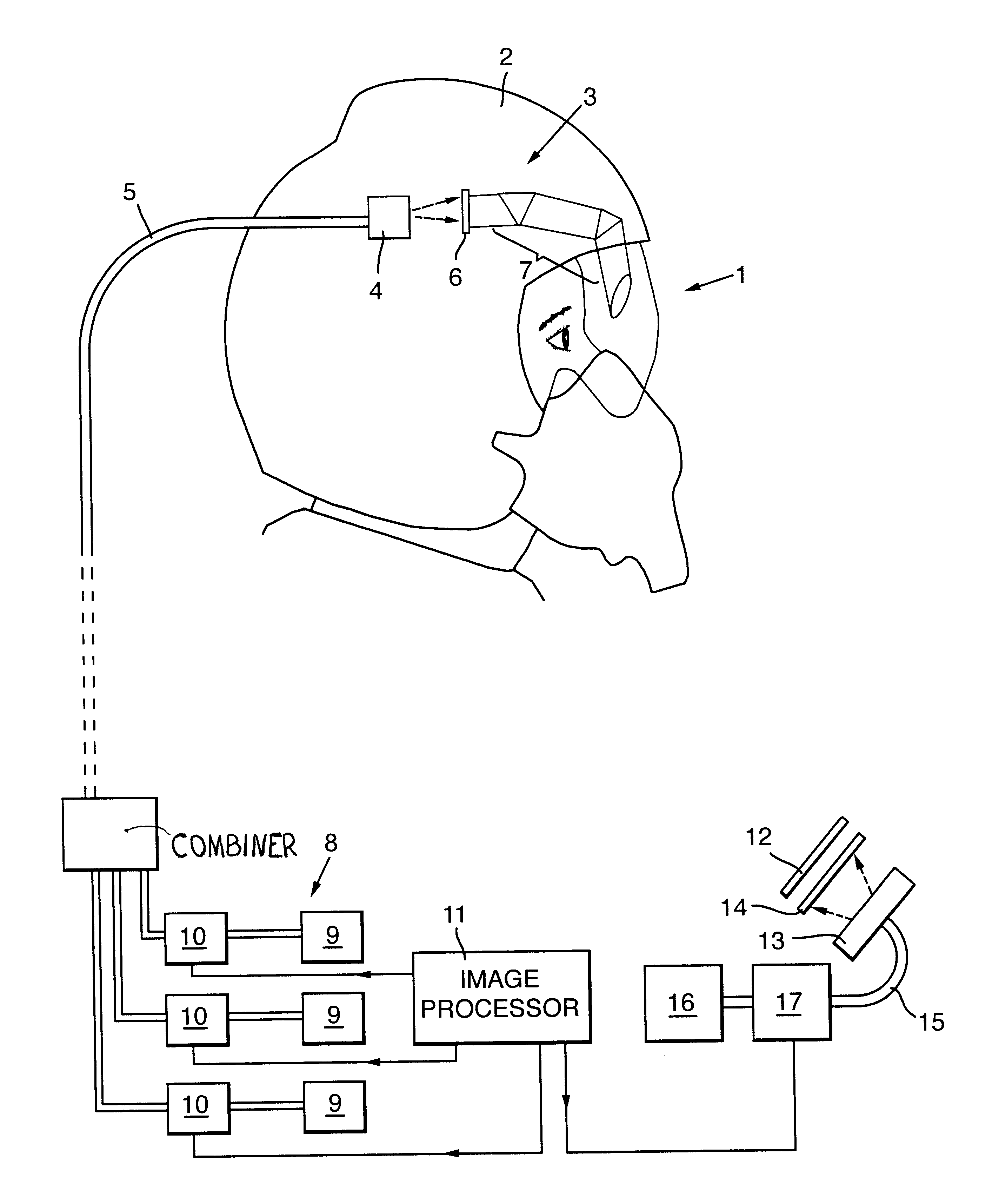
With reference to the FIGURE, an aircraft pilot 1 wears a helmet 2 on which is mounted a display arrangement shown generally at 3 which is arranged to present an image to him on a visor or combiner.

The display arrangement 3 includes an acousto-optical scanner 4 for scanning a light beam transmitted to it via an optical fibre bundle 5 across a screen 6 which interfaces with relay optics 7 to transmit the image produced at the screen 6 into the pilot's field of view. The optical fibre bundle 5 is connected at its other end, remote from the helmet 2, to a light source 8 comprising a plurality of lasers 9 having outputs at respective different wavelengths and a plurality of modulators 10 associated with respective ones of the lasers 9.

An image processor 11 is connected to the modulators 10 to control the outputs of the light source 8, the light beams being combined following modulation and transmitted along the optical fibre 5 to the scanner 4. The scanner 4 causes the modulated light b...


PUM


Abstract

A display arrangement particularly suitable for replacing a conventional CRT in a pilot's helmet mounted display includes a light source having a modulated output which is scanned by a scanner across a screen to produce an image. The image is transferred into the pilot's field of view by relay optics. The scanner and screen are mounted on the pilot's helmet and the light source is remote therefrom.

Description

This invention relates to display arrangements and more particularly, but not exclusively, to helmet-mounted displays used by aircraft pilots.BACKGROUND TO THE INVENTIONIn a conventional helmet-mounted display, a small cathode ray tube (CRT) is mounted on the helmet of the pilot or other member of the air crew. The electron beam of the CRT is scanned over its faceplate to generate an image. Specially designed relay optics interface with the CRT faceplate to convey the image into the field of view of the pilot, typically being presented on a combiner attached to the helmet. The relay optics are generally quite complex, involving several elements for focussing and directing the image, and require a significant degree of design effort to integrate them with the CRT and with the part of the system which the pilot actually views. For example, if the image is to be projected onto a visor, the curvature of the visor, which may present a complex optical surface, must be taken into account. ...

Claims


Application Information

Patent Timeline
Patent Type & Authority Patents(United States)
IPC IPC(8): G02B27/01H04N5/64G02B27/02G09G3/20G09G5/00
CPCG02B27/0172G02B27/017
Inventor BARTLETT, CHRISTOPHER T
Owner BAE SYSTEMS PLC
Why Eureka
Try Eureka