Cause effect diagram program

a diagram and program technology, applied in the field of cause effect diagrams, can solve problems such as time-consuming methods

Inactive Publication Date: 2002-04-09
SCHNEIDER ELECTRIC SYST USA INC
View PDF7 Cites 117 Cited by
  • Summary
  • Abstract
  • Description
  • Claims
  • Application Information

AI Technical Summary

Problems solved by technology

However, this method is time consuming and subject to errors caused by misinterpretation of CEM which serves as the specification or inaccurate coding between that which is specified by the CEM and implementation into FBD program or an LD language.

Method used


Image

  • Cause effect diagram program
  • Cause effect diagram program
  • Cause effect diagram program

Examples


Embodiment Construction

)

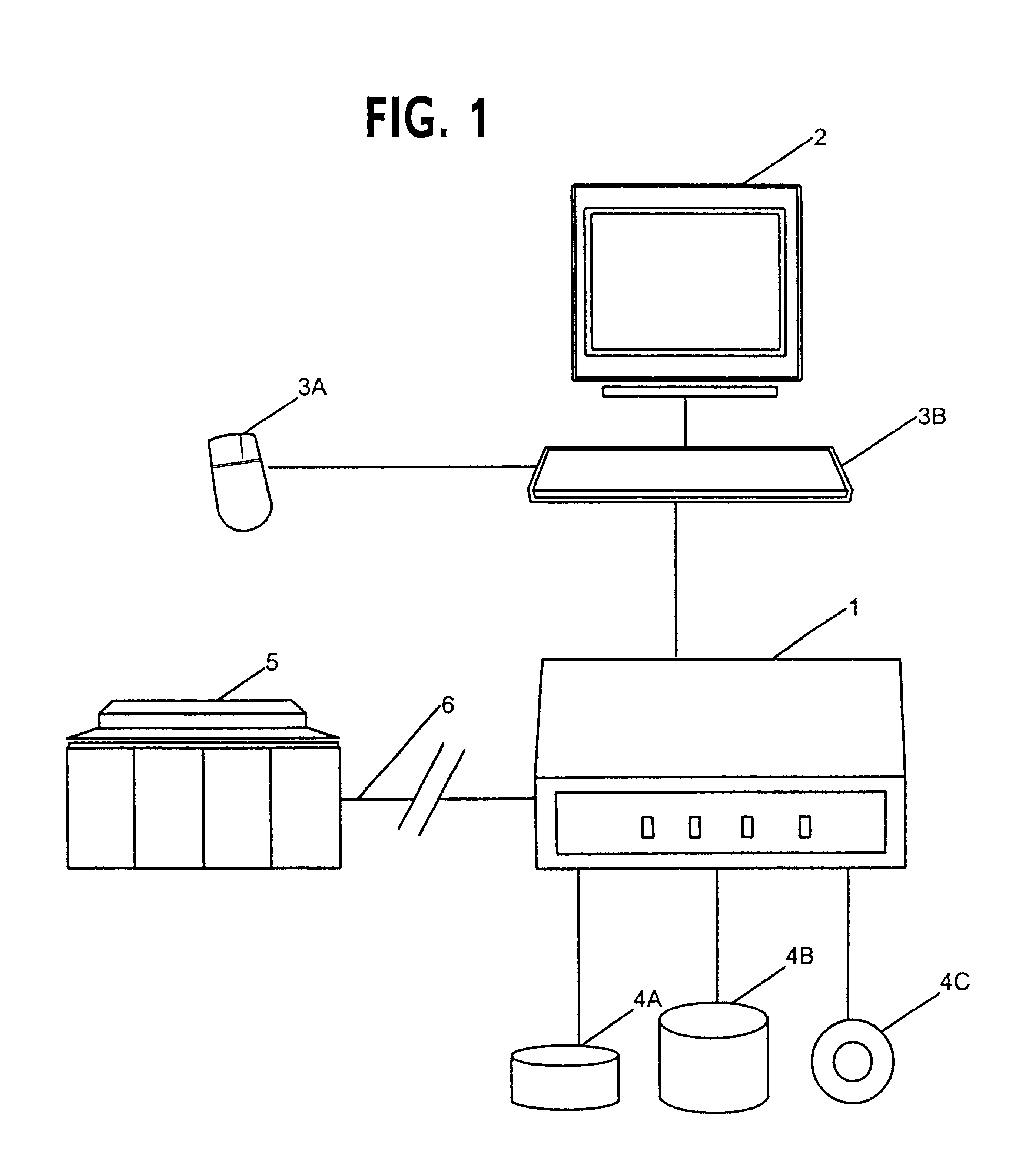
Referring now to the drawings, FIG. 1 shows a personal computer system 1, with a monitor 2, a mouse 3A and a keyboard input 3B. The computer system 1 includes computer readable memory (both internal to the system and not shown) and a floppy diskette drive 4A, a fixed disk storage drive, 4B and a CD ROM drive 4C. The computer system is connected to a safety system 5 over a communications link 6. Once code is tested and compiled into executable code for the microprocessor of the target safety system, it is downloaded over the communications link 6 to the safety system 5, in the preferred case, a TRICON triple redundant safety control system manufactured by Triconex Corporation. The CEM programming system implemented on computer system 1, is also provided by Triconex Corporation on a Triconex TRISTATION 1131 PC which is used to develop safety system programs. Although virtually any computer system may be used for CEM development, the preferred minimum system requirements are as follow...


PUM


Abstract

A computer system for generating a cause effect matrix as a user interface to develop a control program based on the cause effect matrix and to compile and download the resulting program into a programmable controller. A cause effect matrix diagram is used to develop a function block diagram program which is a standard IEC 1131-3 language. The function block diagram is translated into structured text which is compiled into intermediate code. The intermediate code is translated into the native code for the micro-processor of the target control system, including but not necessarily limited to the Motorola processor MPC-860. The automation of a cause effect matrix diagram to generate a function block diagram permits additional capability by allowing functions for causes, intersections, and effects. Because special functions may be included, the results of a cause generate timing functions or other computations before initiating the effect.

Description

1. Field of the InventionThis invention relates generally to visual programming systems and the conversion of such systems to intermediate or executable code. More particularly, this invention relates to a cause effect matrix format used to analyze functions in programming systems which is then used to generate other visual program elements such as Functional Block Diagrams, Structured Text or Ladder logic which is compiled into executable code.2. Description of the Related ArtCause effect matrix (CEM) diagrams have been prepared for many years, and are used to develop a logic system which is placed into a cause and effect diagram in a readable matrix format. Software programs have been developed to evaluate functional block diagrams and generate cause and effect diagrams for audit purposes. Most notable of these is the Trebelex Program which operates under Microsoft Word's DOS system. Trebelex is a manual diagramming tool that is primarily used to translate product logic to a paper...

Claims


Application Information

Patent Timeline
Patent Type & Authority Patents(United States)
IPC IPC(8): G06F3/00G05B19/042G05B19/05G06F9/44G06F9/445
CPCG05B19/0426G05B19/056G06F8/34G05B2219/13106G05B2219/13136Y10S715/965G05B2219/23279G05B2219/23293Y10S715/967G05B2219/23272
Inventor LARSON, DAVID P.POWERS, LESLIE V.HOCKER, ROBERT A.
Owner SCHNEIDER ELECTRIC SYST USA INC
Why Eureka
Try Eureka