Method for metal melting, refining and processing

a metal melting and refining technology, applied in the field of metal melting, refining and processing, can solve the problems of furnace walls and surrounding furnace equipment being damaged, burners and lances previously used to provide this function were not very successful and efficient, and the danger of damage is greates

Inactive Publication Date: 2002-04-16
PROCESS TECH INT
View PDF2 Cites 72 Cited by
  • Summary
  • Abstract
  • Description
  • Claims
  • Application Information

AI Technical Summary

Problems solved by technology

When a long electric arc is struck, the radiative component of the arc above the bath can cause degradation to the furnace walls and the surrounding furnace equipment.
The danger of this damage occurring is greatest after a significant portion of the scrap has been melted and the walls of the furnace are exposed to heat radiation from the arc and similarly thereafter during refining and flat bath conditions.
The burners and lances previously used to provide this function were not very successful and efficient as they could be, because they direct the flows of carbon and oxygen in different directions.
A straight conduit is conventional because the particulates injected into a steel making furnace are highly abrasive and will wear out bends or other restrictions to their flow quickly.
This is one of the reasons why particulates have not be injected through the same conduit as the one used for supersonic oxygen of a burner, the particulates would quickly wear out the converging restriction of the nozzle.
A central conduit is preferred because it is highly disadvantageous to break the stream into more than one flow because one would like to concentrate particulates in a specific area.
However, the carbon injection is not coaxial to the stream of oxidizing gas introduced through the burner and cannot be directed in sufficient quantities to be advantageous.
This configuration is highly disadvantageous due to the small supersonic openings and dispersion of the supersonic oxygen due to flow turbulence of each small aperture interacting with that of the other apertures.
Lances which have to be moved require relatively expensive lance manipulators and openings in the furnace through which they are positioned.

Method used


Image

  • Method for metal melting, refining and processing
  • Method for metal melting, refining and processing
  • Method for metal melting, refining and processing

Examples


Embodiment Construction

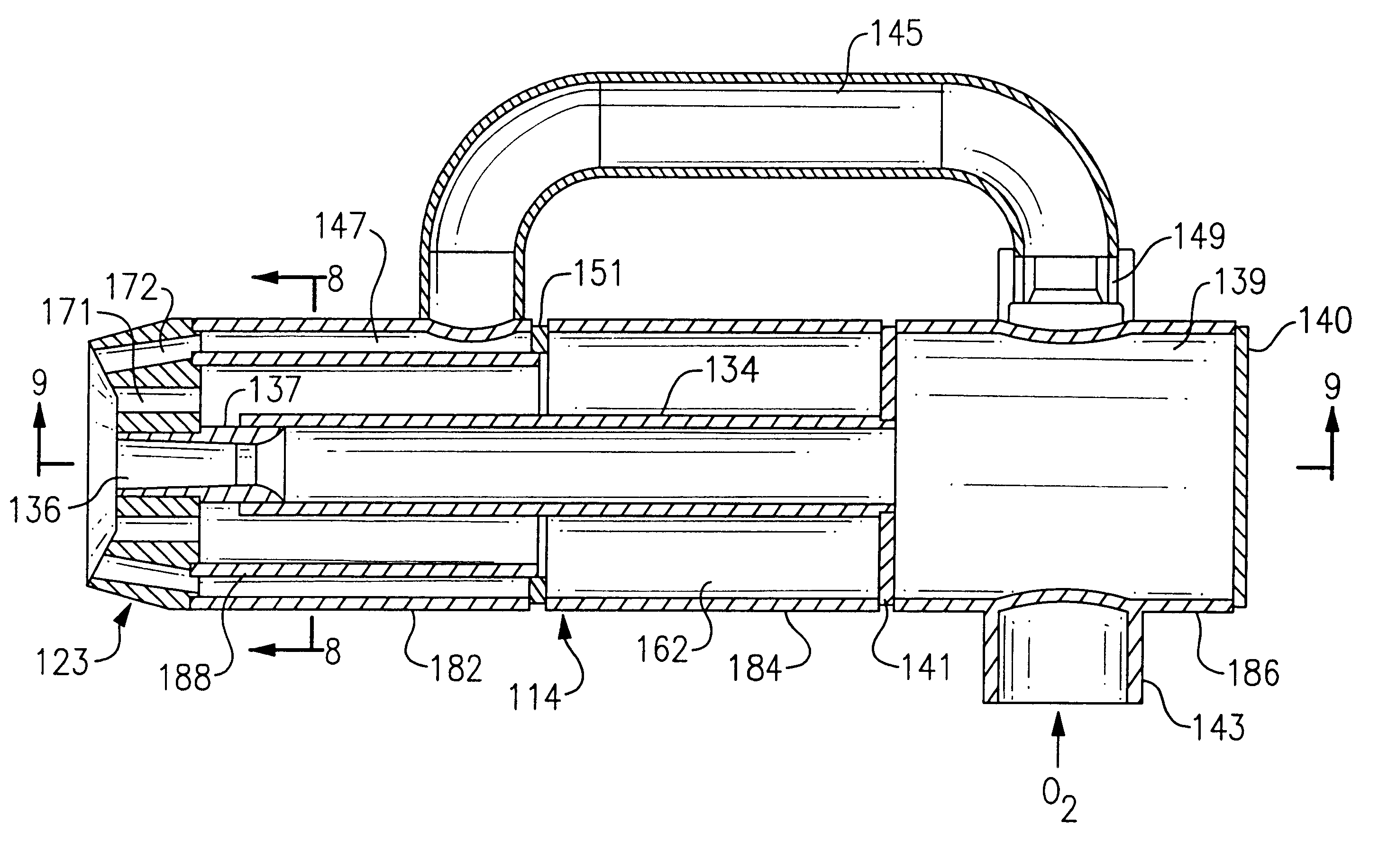
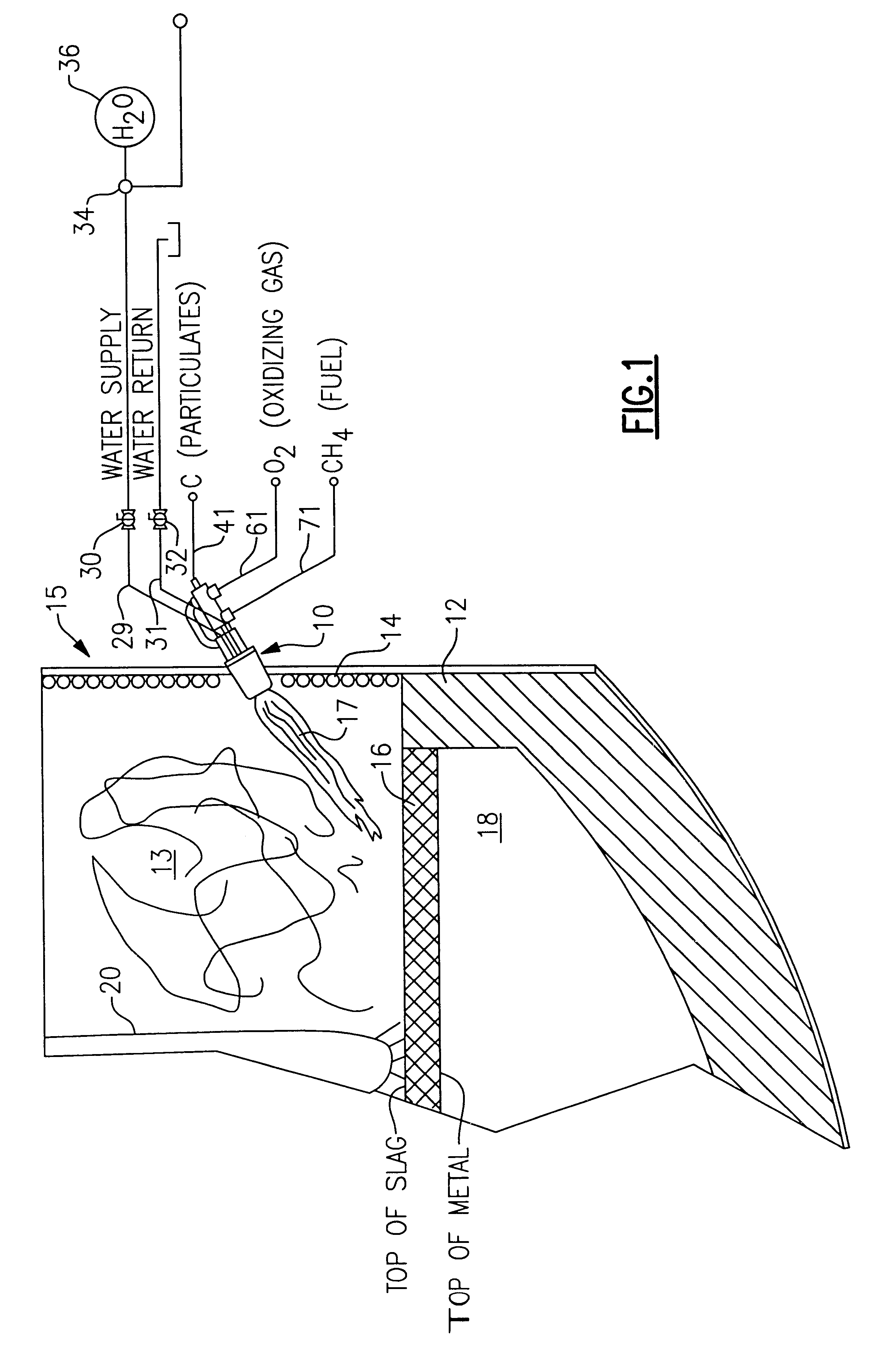
A burner or apparatus 10 constructed in accordance with the invention is shown to advantage in FIG. 1. The burner 10 is adaptable to operate in several different modes to provide auxiliary heating, metal refining and other metallurgical processing capabilities in an electric arc furnace (EAF) 15, or other metal melting, refining and processing furnaces. The EAF 15 melts ferrous scrap 13, or other iron based materials, by means of an electric arc produced from one or more electrodes 20 to collect a molten metal melt 18 at its bottom. The melt 18 is generally covered with various amounts of slag 16 which is produced by chemical reactions between and the melt and slag forming materials added to the furnace before or during the melting process of the metal. Once the metal has been melted, the heat is generally refined or decarburized by oxygen lancing. This reduces the carbon content of the metal to the grade of steel desired. During refining and thereafter, the melt is typically heated...


PUM

PropertyMeasurementUnit
angleaaaaaaaaaa
velocityaaaaaaaaaa
thermal energyaaaaaaaaaa

Abstract

An improved method and apparatus for metal melting, refining and processing, particularly adapted to steel making in an electric arc furnace. The method provides auxiliary thermal energy to the steel making process, particulate injection for the formation of slag and foamy slag, and oxygen injection for the decarburization of the melt, for the formation of foamy slag and for post combustion burning of carbon monoxide. The burner includes two injection barrels for providing finely pulverized particles and for providing either a supersonic or a subsonic primary flow of an oxidizing gas. The barrels are positioned side by side in a nozzle at the entrance of a flame shaping chamber of a fluid cooled combustion chamber. The nozzle also contains a plurality of fuel orifices for the providing pressurized fuel to the combustion chamber and a plurality of oxidizing gas orifices for providing a secondary flow of an oxidizing gas around the periphery of the nozzle. Because all of the flows of fuel, oxidizing gas and particulates pass through the flame shaping chamber, they are all substantially directed to the same location in the electric arc furnace. The directionality of the flows allows the burner to heat a localized spot of the slag with thermal energy from the oxidation of the fuel, from the oxidation of oxidizable components in the slag or the melt by the lancing of supersonic oxidizing gas, or from any combination of these. Once a spot in the slag is sufficiently heated, a flow of carbon is directed to the localized hot spot in the slag to reduce the FeO, and other oxides, in the slag to carbon monoxide and produce foamy slag. The particulate carbon introduction can be accompanied by further oxidizing gas injection before, during or after the carbon injection.

Description

1. Field of the InventionThe present invention generally relates to an improved method and apparatus for metal melting, refining and processing, for example, steel making in an electric arc furnace (EAF), and more particularly, to an auxiliary burner or lance for the addition of thermal energy by the combustion of fuel, the injection of oxidizing gas for melt refining, foamy slag production or post combustion of carbon monoxide, and the injection of particulates for slag and foamy slag production.2. Description of Background ArtOxygen and carbon lances are known in the art of metal melting, refining and processing, particularly steel making, to be useful for the injection of carbon and oxygen for many steps in the process. In addition, auxiliary burners have been used to provide additional thermal energy and supersonic oxygen to these processes.An electric arc furnace makes steel by first using an electric arc to melt one or more charges of scrap metal which is placed within the fur...

Claims


Application Information

Patent Timeline
Patent Type & Authority Patents(United States)
IPC IPC(8): C21C5/00C21C5/52C21C5/54
CPCC21C5/54C21C5/5217Y02P10/20
Inventor SHVER, VALERY G.PULLIAM, TERRY E.
Owner PROCESS TECH INT
Why Eureka
Try Eureka