Floating interface for integrated circuit test head

a technology of integrated circuits and test heads, applied in electrical testing, measurement devices, instruments, etc., can solve the problems of difficult to achieve fine position adjustments of such a large mass, 500 pounds, and large test head weigh

Inactive Publication Date: 2002-04-23
CREDENCE SYSTEMS
View PDF6 Cites 74 Cited by
  • Summary
  • Abstract
  • Description
  • Claims
  • Application Information

AI Technical Summary

Problems solved by technology

One problem with this approach is the test head can be quite massive, for example 500 pounds or more.
Fine position adjustments of such a large mass are difficult to achieve.
Since the massive test head has much inertia, relatively large forces must be applied to move it into position with reasonable speed, and the stresses involved with using large forces to move a massive object take their toll on parts.
Other structural factors also contribute to the difficulty of making proper alignment of the test head.
This limits our ability to adjust the plane of the pogo pin tips.
Also the X axis about which the head can rotate passes through or near the center of gravity of the test head rather than through the contact pads, thereby making the movements needed for precise alignment complicated.

Method used


Image

  • Floating interface for integrated circuit test head
  • Floating interface for integrated circuit test head
  • Floating interface for integrated circuit test head

Examples


Embodiment Construction

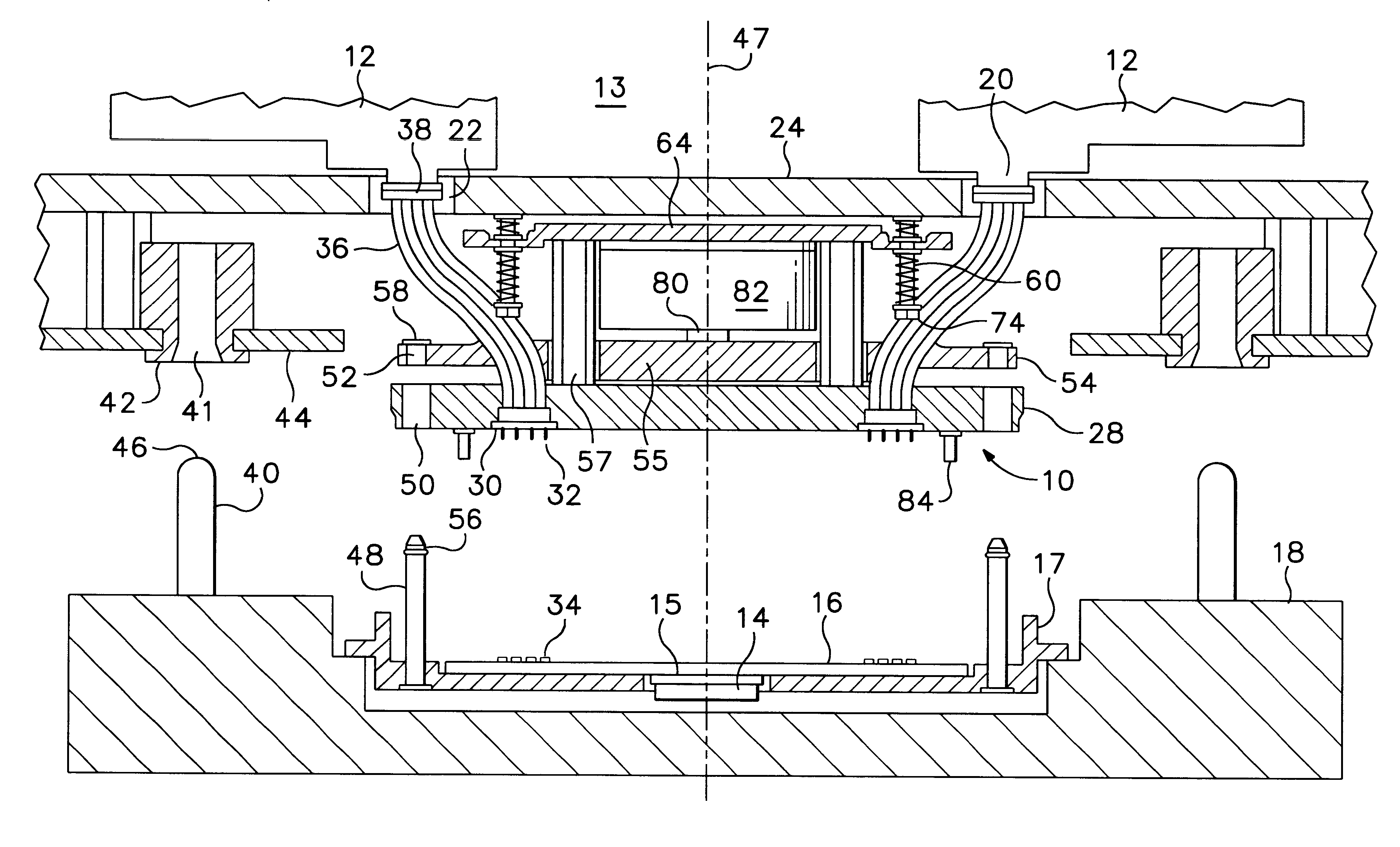
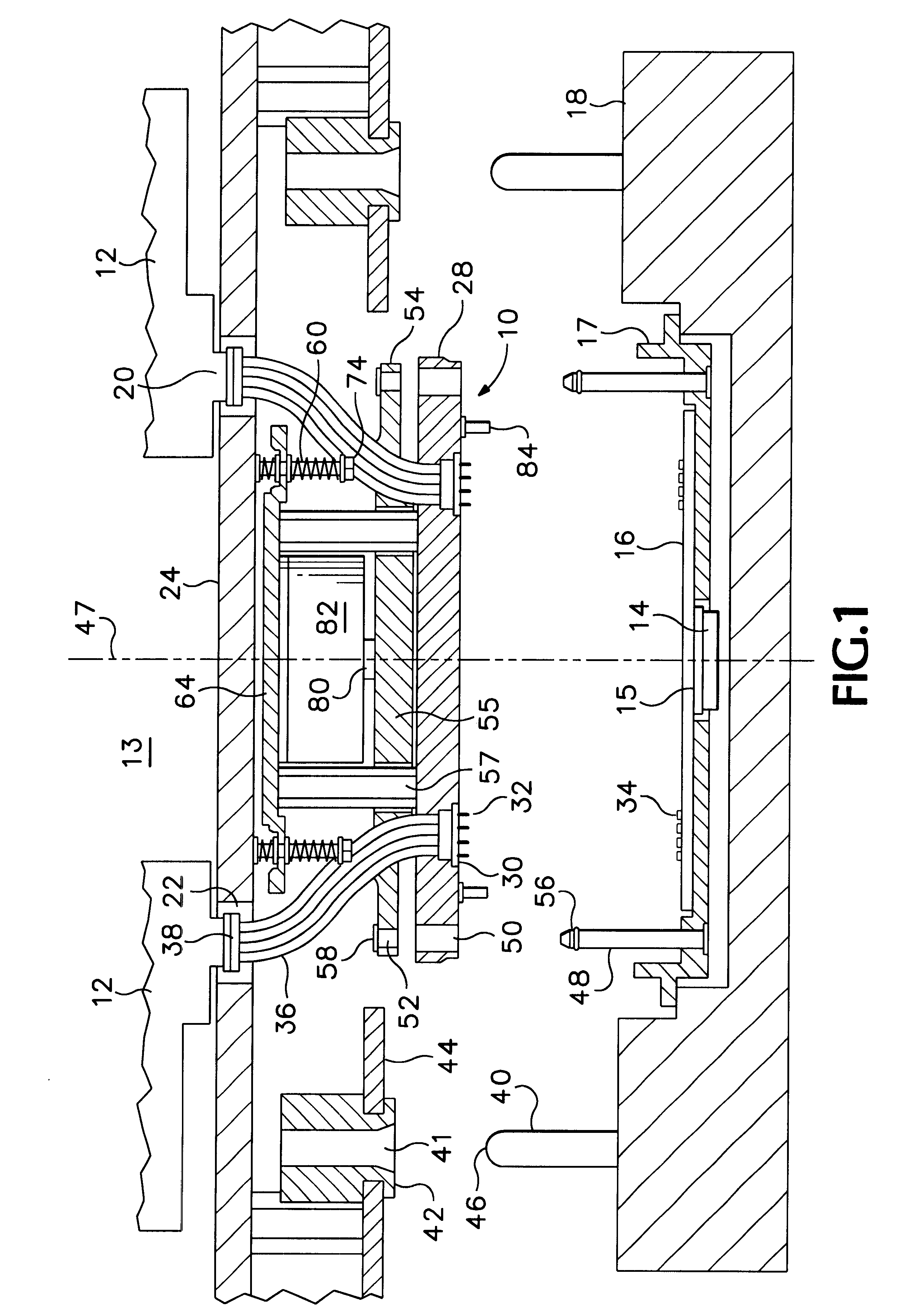
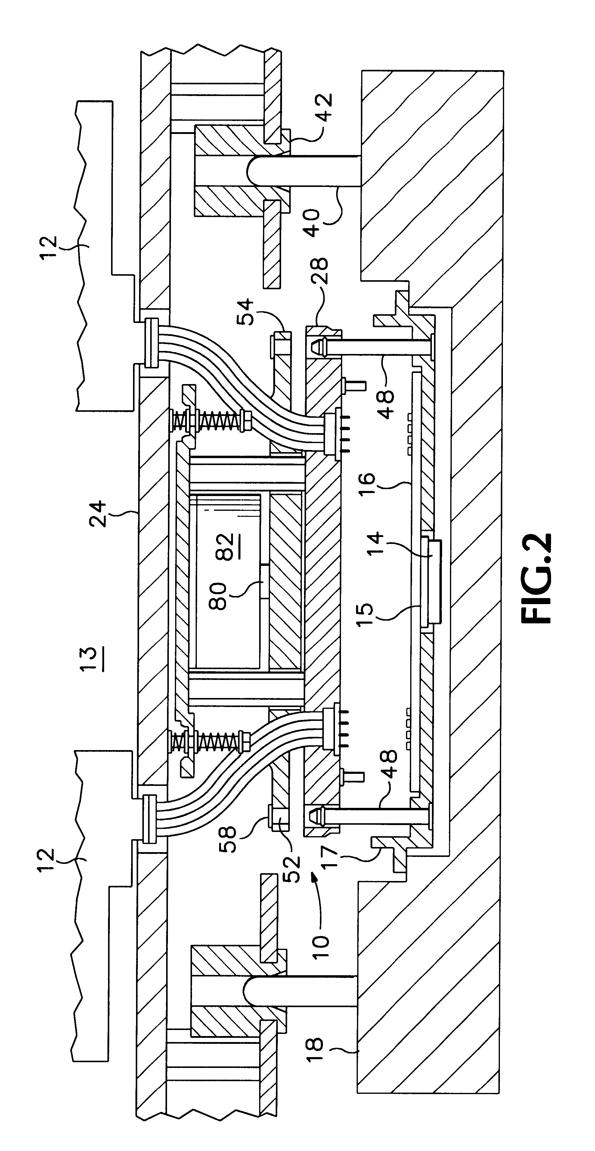
FIGS. 1-4 are sectional elevation views of a floating interface assembly 10 in accordance with the invention for helping interconnect test circuits implemented on pin cards 12 mounted with an integrated circuit (IC) tester's test head 13 with one or more integrated circuits 14 to be tested. FIG. 5 is a plan view of a base plate of the floating interface assembly of FIGS. 1-4 and FIG. 6 is a perspective view of portions of the floating interface assembly of FIGS. 1-4.

Referring to FIGS. 1-6, the packaged IC 14 is installed in a socket 15 on an underside of a printed circuit board ("load board") 16 residing on a carrier platform 17 mounted adjacent to test head 13 on a conventional IC handler (or prober) 18. For simplicity, only one IC 14 is shown mounted on load board 16, but several ICs to be tested concurrently may be mounted together on a single load board 16.

During a test, tester channels implemented on pin cards 12 transmit test signals to IC 14 and monitor output signals produce...


PUM


Abstract

A floating interface assembly provides signal paths between an integrated circuit (IC) test head and contact pads on a load board or probe card accessing an IC to be tested. Pogo pins or other contactors for contacting the contact pads are mounted on the interface assembly and linked to the test head by flexible conductors. The interface assembly is attached to the test head by springs to allow it the freedom to rotate to some extent about any axis. As the test head approaches the contact pads, alignment pins engage and orient the interface assembly so that its contactors will mate with the contact pads. As the contactors come into contact with the contact pads, the interface assembly adjusts the plane of the contactors so as to evenly distribute contact pressure over all contactor pads.

Description

1. Field of the InventionThe present invention relates in general to systems for aligning the test head of an integrated circuit tester with an integrated circuit device under test (DUT) and in particular with a floating interface for a test head.2. Description of Related ArtAn integrated circuit (IC) tester tests an IC device such as a packaged IC or a die on an IC wafer by transmitting test signals to the device under test (DUT) and monitoring the output signal the DUT produces in response to the test signals. A IC tester includes a separate channel for each input / output (I / O) terminal or test point of the DUT, with each channel being capable of generating and transmitting a test signal to a corresponding DUT terminal or receiving and processing a DUT output signal produced at that terminal. The tester channels are typically implemented on circuit boards mounted in a relatively large chassis called a "test head". While a DUT usually has a large number of input / output (I / O) termina...

Claims


Application Information

Patent Timeline
Patent Type & Authority Patents(United States)
IPC IPC(8): G01R1/073
CPCG01R1/07378
Inventor RAMOS, CARLOSWONG, RICHARDPENG, SIDNEYCOLLINS, DAVIDBAKER, DAVID
Owner CREDENCE SYSTEMS
Why Eureka
Try Eureka