

Fuse and battery pack containing the fuse
a fuse and battery pack technology, applied in the direction of batteries, primary cell maintenance/servicing, cell components, etc., can solve the problems of large size of the whole fuse, difficulty in being conveniently fitted to a narrow position, and difficulty in precisely setting the value of current to be interrupted, so as to ensure the effect of interrupting current and safe use of the battery pack
Inactive Publication Date: 2002-04-23
SANYO ELECTRIC CO LTD
View PDF8 Cites 80 Cited by
- Summary
- Abstract
- Description
- Claims
- Application Information
AI Technical Summary
Benefits of technology
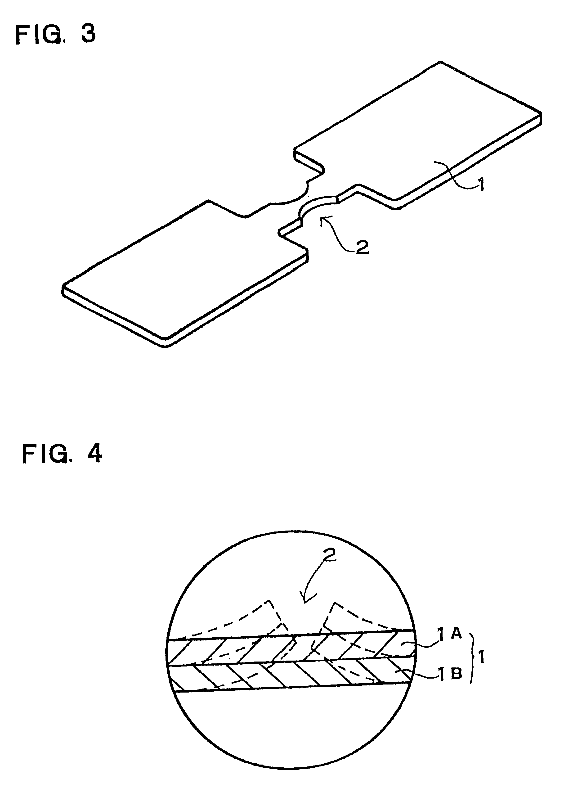
A fuse having this structure is advantageous in that it can precisely set interruption current, can widely change interruption current and further, can be rapidly melted and cut off by interruption current to interrupt current. It is because, when such fuse is heated by overcurrent and thereby melted and cut off, a mechanical deforming force is applied to melted portion, which force is caused by difference between the thermal expansion coefficients of the metal plates constituting a different thermal expansion coefficient metal laminate. When a different thermal expansion coefficient metal laminate is heated by overcurrent, different amount of deformation is generated through the laminate, which causes a mechanical deforming force to be applied to a melting portion of the fuse. With this mechanical deforming force, a fuse is precisely and rapidly melted and cut off at the melting portion. Therefore, a fuse having this structure can realize advantages of precisely setting interruption current, of widely changing interruption current, and further, of rapidly being melted and cut off by interruption current to interrupt current. Further, a fuse having this structure has an advantage of surely cutting off melted portion to interrupt current, since the melting portion of the fuse is thermally mechanically deformed and cut off by means of a different thermal expansion coefficient metal laminate.
Furthermore, unlike a conventional fuse, a fuse having this structure is not melted and cut off at a portion connected to a terminal, but is cut off at the melting portion to which a mechanical deforming force is applied by difference between thermal expansion coefficients of the metal plates constituting the different thermal expansion coefficient metal laminate, so that the whole of a fuse need not be large in size, and it can be conveniently fitted to a narrow portion. In other words, the whole of a fuse having this structure can be formed compact in size and conveniently applied to a variety of uses.
A battery pack having this structure can rapidly melt and cut off a fuse and thereby can interrupt current when the battery pack is used in abnormal state. It is because a fuse connected in series to the battery comprises a different thermal expansion coefficient metal laminate in which a plurality of different thermal expansion coefficient metal plates are laminated.
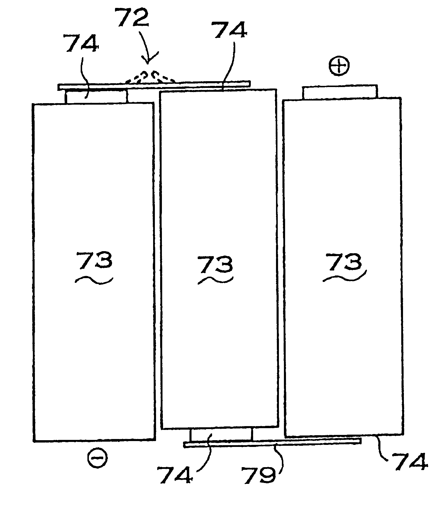
A battery pack having this structure has an advantage that, since a melting portion of a fuse melted and cut off by overcurrent is deformed in the direction separated from a battery, the melted fuse can be prevented from attaching to the battery, thereby affording to surely interrupt current and safely use the battery pack.
Problems solved by technology
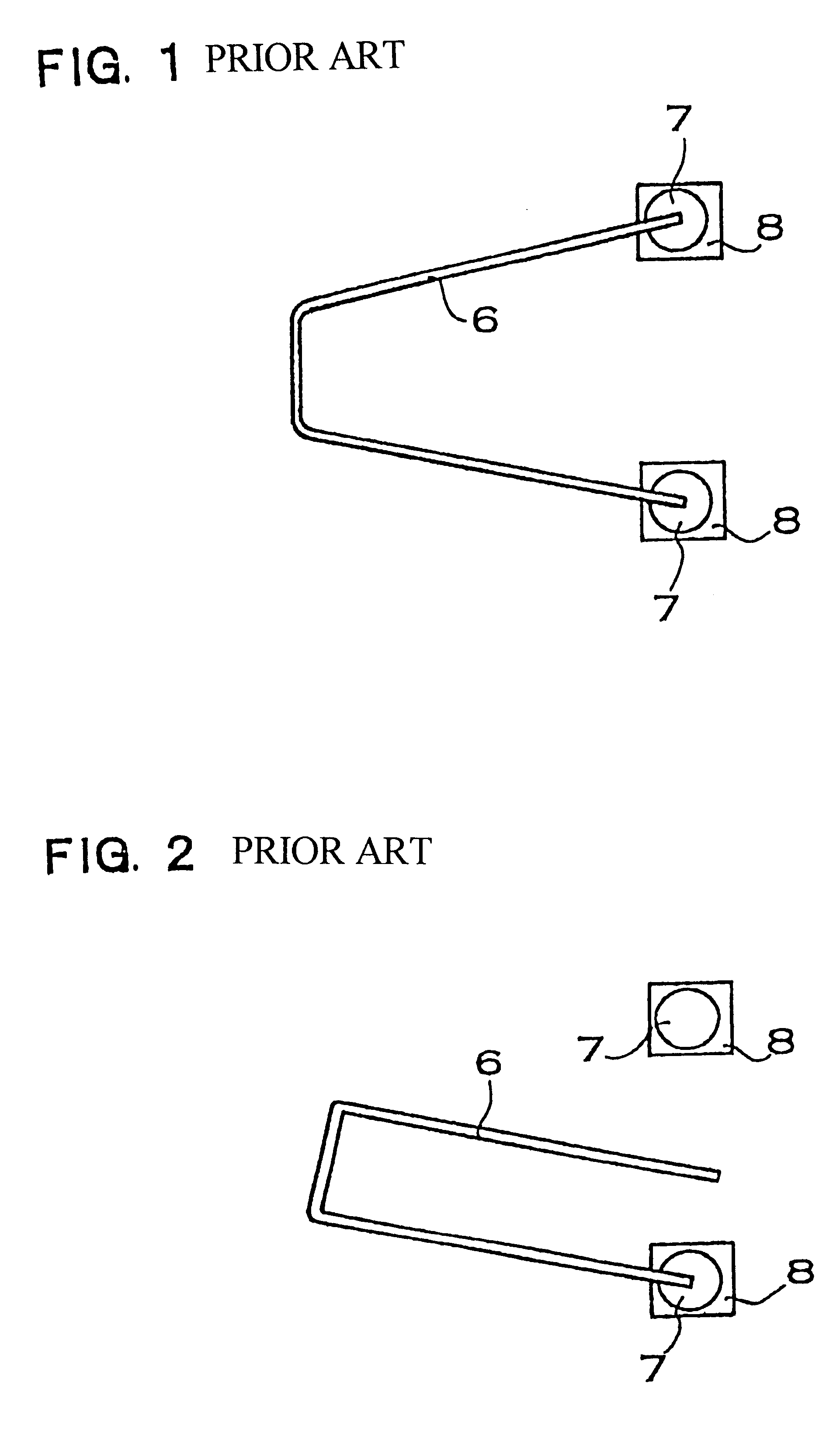
And whole of such a fuse becomes large in size, and it has a difficulty in being conveniently fitted to a narrow position.
Further, in a fuse having this structure, since a conductive substance of low melting point such as a solder is melted to interrupt current, it is difficult to precisely set the value of current to be interrupted.
This makes it difficult to precisely set the value of current to be interrupted, which is hereinafter referred to as "interruption current".
Further, it is difficult to widely change melting temperature of a solder, in other words, widely change interruption current.
It is especially difficult to make interruption current small.
Method used
View moreImage
Smart ImageViewing Examples

Examples
example 1
A fuse was manufactured by way of trial similarly to EMBODIMENT 1 except that a Mn--Ni--Cr alloy was used instead of a different thermal expansion coefficient metal laminate. Volume resistivity of this alloy was 120 .mu..OMEGA..multidot.cm.
example 2
A fuse was manufactured by way of trial similarly to EMBODIMENT 1 except that a SUS304 stainless plate was used instead of a different thermal expansion coefficient metal laminate. Volume resistivity of this stainless plate was 85 .mu..OMEGA..multidot.cm.
example 3
A fuse was manufactured by way of trial similarly to EMBODIMENT 1 except that a Fe--Ni alloy plate was used instead of a different thermal expansion coefficient metal laminate. Volume resistivity of this alloy plate was 64 .mu..OMEGA..multidot.cm.
Login to View More PUM
| Property | Measurement | Unit |
|---|---|---|
| current | aaaaa | aaaaa |
| current | aaaaa | aaaaa |
| current | aaaaa | aaaaa |
Abstract
A fuse is melted and cut off when an overcurrent flows through the fuse. The fuse has a different thermal expansion coefficient metal laminate obtained by laminating a plurality of different thermal expansion coefficient metal plates. When the fuse is melted and cut off by heat of the overcurrent, a mechanical deforming force is applied to a melting portion of the fuse. The mechanical force is caused by the difference between thermal expansion coefficients of the different thermal expansion coefficient metal plates.
Description
This application is based on applications No. 11-49895 filed in Japan on Feb. 26, 1999 and No. 11-154714 filed in Japan on Jun. 2, 1999, the content of which incorporated hereinto by reference.This Invention relates to a fuse melted and cut off by heat when overcurrent flows and a battery pack containing the fuse.A fuse is melted and cut off by heat when overcurrent flows, and thereby it interrupts current. A fuse is heated by Joule heat. Joule heat increases in proportion to the product of the square of current and resistance of the fuse. Therefore, when current becomes large, Joule heat abruptly increases and a fuse is heated to a high temperature. A fuse is melted at a predetermined temperature which is decided by the kind of the metal used for the fuse. Therefore a fuse is melted and cut off by heat when predetermined current flows and thereby current is interrupted.It is important that a fuse melted and cut off by predetermined current can be rapidly melted and cut off and can ...
Claims
Login to View More Application Information
Patent Timeline
 Patent Type & AuthorityPatents(United States)
IPC IPC(8): H01H85/36H01H85/00H01M2/20H01M2/34H01M6/00H01M6/50H01H85/02H01H85/08H01H85/06H01H85/10H01H85/12H01M50/583
CPCH01H85/36H01M2/348H01M2/34H01H2085/0258H01M2200/103Y02E60/10H01M50/581H01M50/583
InventorHASHIMOTO
OwnerSANYO ELECTRIC CO LTD