
Method and system for oriented perforating in a well with permanent sensors

a technology of perforation and well, applied in the field of perforation casings of hydrocarbon wells, can solve the problems of inconvenient use, inconvenient use, damaged or destroyed techniques,

Inactive Publication Date: 2002-04-30
SCHLUMBERGER TECH CORP
View PDF8 Cites 60 Cited by
  • Summary
  • Abstract
  • Description
  • Claims
  • Application Information

AI Technical Summary

Benefits of technology

Thus, it is an object of the present invention to provide an apparatus and method for orienting a perforation gun in a borehole so as to avoid perforating a cable or sensors located in the area to be perforated.
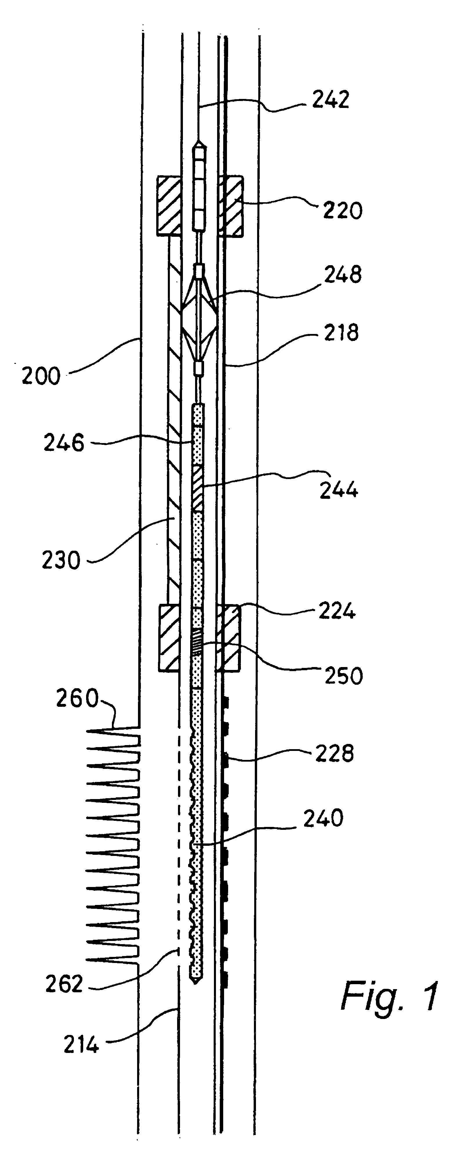
According to the invention, a method is provided for perforating a conduit in a hydrocarbon well so as to avoid perforating in a direction where a cable resides. A mass of preferably metallic material is fixed to the conduit at a predetermined offset angle with respect to the cable. The angular position of the mass of material is detected using a detector adapted to sense the mass of material. A perforation device is oriented based on the angular position of the mass of material and the predetermined offset angle, such that the perforation device will create perforations in the conduit in a direction substantially away from the cable. Finally, the conduit is perforated so as to avoid substantial damage to the cable.

Problems solved by technology

If the perforations are made in the direction of such a cable, the cable could be perforated, damaged, or destroyed.
However, this technique may not be suitable for avoiding cables and the like since the exact direction of the cable may not be known due to unintended twisting or turning of the cable and casing.
Furthermore, the use of swivels and rollers this is not suitable in vertical wells as gravity is not available to assist in the orientation.
Directly sensing the location of the cable has difficulties as well.
For example, a cable cemented in place outside the casing is not easily detected with instruments placed inside the casing during perforation, since the detectable signal from the cable is normally either non-existent, or too weak to be a reliable indicator of the cable location.

Method used


Image

  • Method and system for oriented perforating in a well with permanent sensors
  • Method and system for oriented perforating in a well with permanent sensors
  • Method and system for oriented perforating in a well with permanent sensors

Examples


Embodiment Construction

:

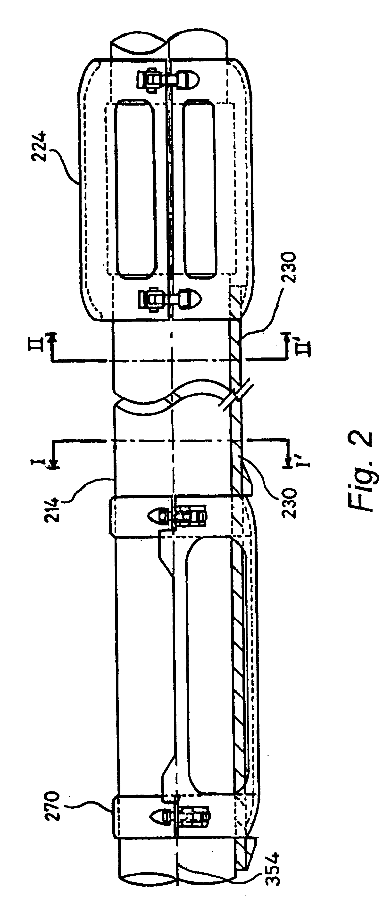
The following embodiments of the present invention will be described in the context of oriented perforation of a casing in the vicinity of a permanent sensor cable, although those skilled in the art will recognize that the disclosed methods and structures are readily adaptable for broader application. For example, the invention is readily adaptable to oriented perforating of casing to avoid damage to other structures besides cables. Note that whenever the same reference numeral is repeated with respect to different figures, it refers to the corresponding structure in each such figure.

FIG. 1 shows a cross-sectional view of an apparatus for oriented perforation according to a preferred embodiment of the invention. Borehole 200 is shown in the vicinity of a hydrocarbon reservoir. Casing 214 is inserted in borehole 200. Although 214 is shown as a casing, the invention is also applicable to tubings within casings as well as other conduits. Along the right side of casing 214 is a cable 2...


PUM


Abstract

A method and system is provided for perforating a casing in a hydrocarbon well so as to avoid perforating in a direction where a cable resides. A mass of metallic material is clamped to the casing at a predetermined offset angle with respect to the cable. The angular position of the metallic mass is detected using a detector placed inside the casing. Then, a perforating gun is oriented based on the detected angular position of the metallic mass and the predetermined offset angle. Finally, the casing is perforated so as to avoid damage to the cable. The cable comprises a number of electrical conductors and is used to communicate with permanent sensors located on the cable in the vicinity of the casing to be perforated.

Description

FIELD OF THE INVENTION:The present invention relates to the field of perforating casings of hydrocarbon wells. In particular, the invention relates to a method and system for oriented perforating of a well casing in the vicinity of a cable such as could be used for permanent sensors.BACKGROUND OF THE INVENTION:As part of the completion process for hydrocarbon wells, a steel casing is placed inside the borehole and subsequently cemented in place. The casing, the cement, and portions of the subterranean formation are then perforated using conventional perforation techniques. Ordinarily, the perforations are made in various directions generally perpendicular to the axis of the borehole in the vicinity of the hydrocarbon reservoir using a perforating gun. In some situations, however, the perforations may need to be made so as to avoid a certain direction. For example, if a cable of some kind is located in the borehole but outside the casing during the perforation process, the perforatio...

Claims


Application Information

Patent Timeline
Patent Type & Authority Patents(United States)
IPC IPC(8): E21B43/11E21B43/119
CPCE21B43/119
Inventor RYAN, SARAH ELIZABETHRAW, IAN
Owner SCHLUMBERGER TECH CORP
Learn More