Measuring condition setting jig, measuring condition setting method and biological information measuring instrument

a technology of condition setting and measuring jig, which is applied in the direction of instruments, diagnostic recording/measuring, applications, etc., can solve the problems of large error, many inconveniences, and large error in measurement conditions, and achieve high accuracy, easy and accurate measurement, and low deviation

Inactive Publication Date: 2002-04-30
KYOTO DAICHI KAGAKU
View PDF37 Cites 101 Cited by
  • Summary
  • Abstract
  • Description
  • Claims
  • Application Information

AI Technical Summary

Benefits of technology

The measurement condition setting fixture also includes a securing section for a measuring optical system, the securing section being secured to the measurement site securing section. A part of the measuring optical system is attached to the securing section for the measuring optical system only at the time of measurement. Thus, throughout the measurement, measurement conditions, such as the angle at which the light is incident on the measurement site, the distance between a light irradiation section of the measuring optical system and the measurement site, the distance between the measurement site and a light receiving section for receiving the light from the measurement site, and the positional relationship between the light receiving section and the measurement site can be maintained at desirable conditions; e.g., the measurement conditions which provide a most precise measuring value.
As described above, when the measurement condi

Problems solved by technology

In general, in optical measurement for irradiating a living body with light and obtaining living body information based on transmitted or reflected light, even a slight change in the site irradiated by light at which a measurement is to be taken (hereinafter, referred to simply as a "measurement site") is a significant cause of error.
However, in the case where the living body is secured to the measuring apparatus, many inconveniences occur when the measurement takes a long time or a routine measurement is performed, such that the person undergoing the measurement cannot be away from the measuring apparatus or only

Method used


Image

  • Measuring condition setting jig, measuring condition setting method and biological information measuring instrument
  • Measuring condition setting jig, measuring condition setting method and biological information measuring instrument
  • Measuring condition setting jig, measuring condition setting method and biological information measuring instrument

Examples


example 2

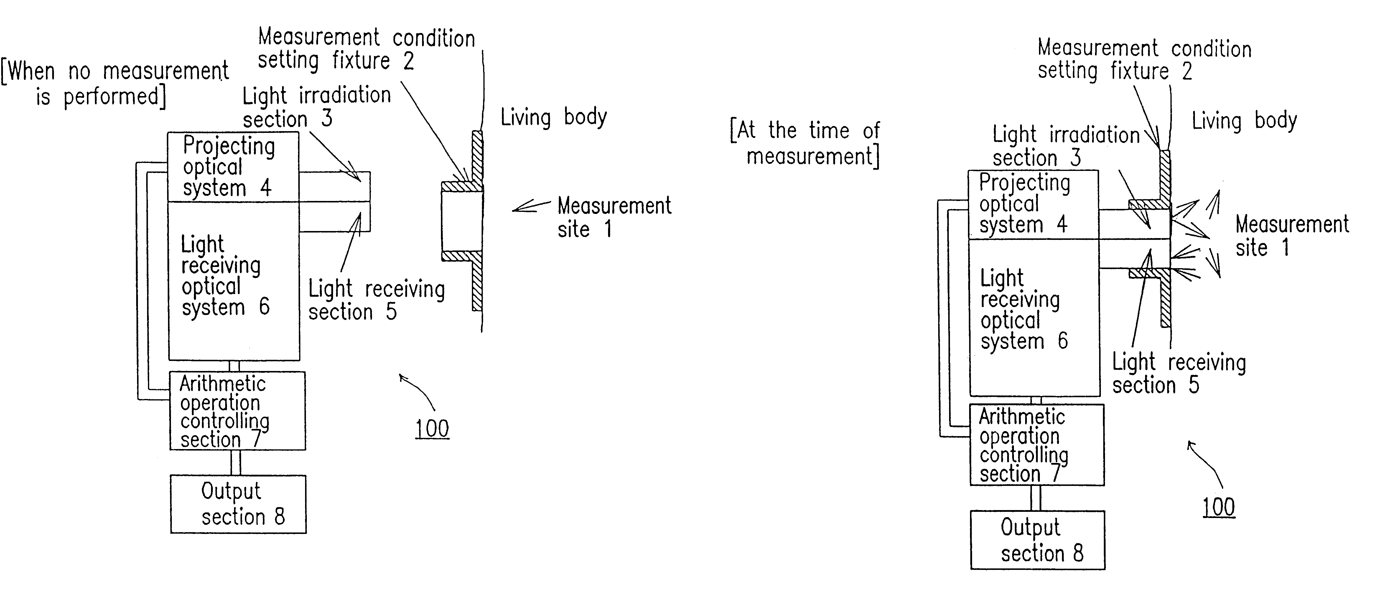
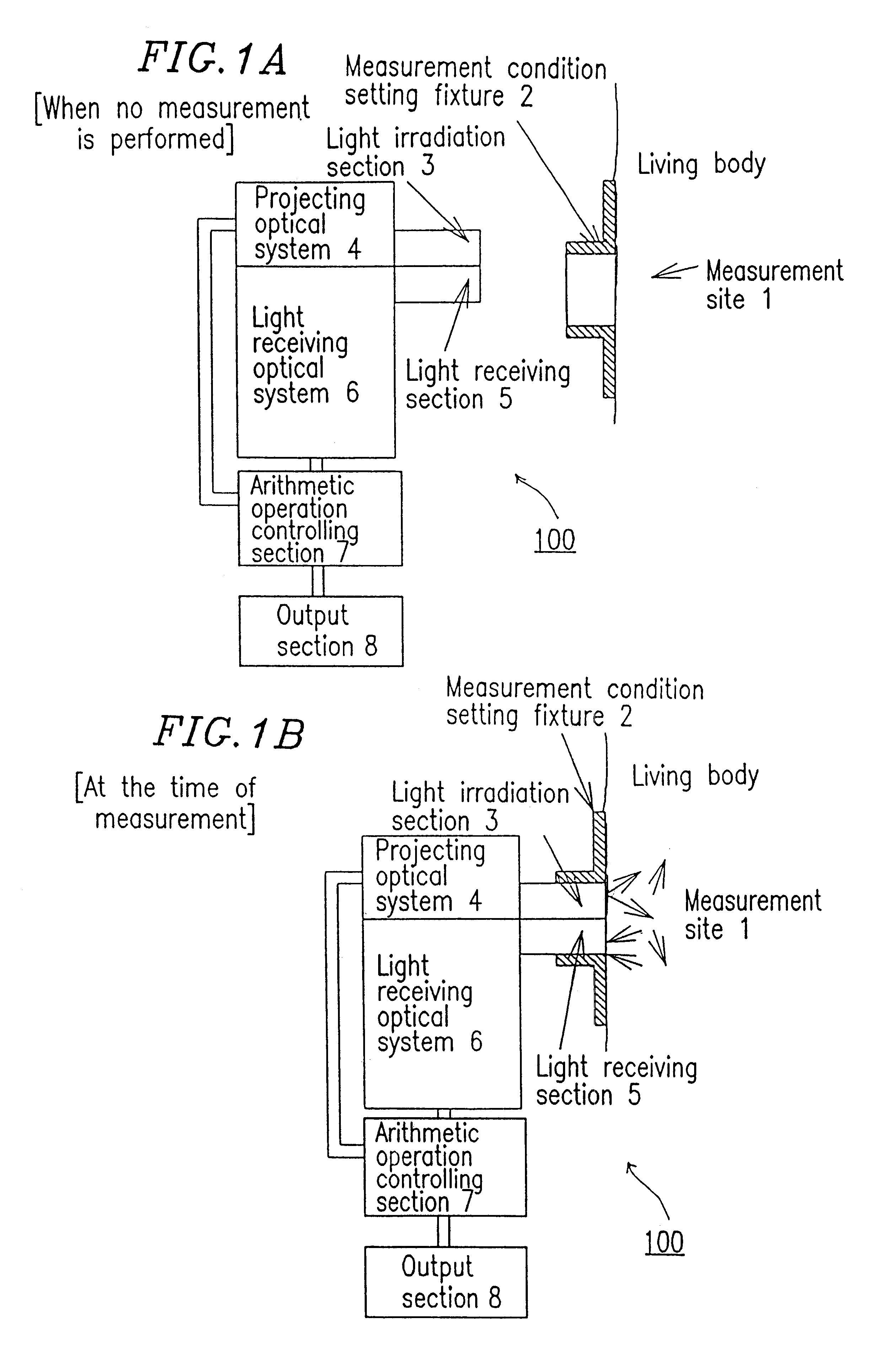
Next, with reference to FIGS. 4A and 4B, a living body information measuring apparatus in a second example will be described. In FIGS. 4A and 4B, identical elements previously discussed with respect to FIG. 1A and 1B bear identical reference numerals and the detailed descriptions thereof will be omitted.

In this example, the measurement condition setting fixture 2 is a ring-shaped or bracelet-shaped. The measurement site 1 and the measurement condition setting fixture 2 are secured to each other by inserting a part of the living body including the measurement site 1 into the setting fixture 2. In this example, the light used for measuring the living body information has been transmitted through the body at the measurement site. Therefore, the light irradiation section 3 and the light receiving section 5 of the measuring optical system are located so as to have the living body therebetween. FIGS. 4A and 4B show respective cross-sections in the state where the measurement condition set...


PUM


Abstract

A measurement condition setting fixture 2 is secured to a measurement site 1 of a living body prior to the measurement. At the time of measurement, a light irradiation section 3 and a light receiving section 5 of a measuring optical system are respectively attached and secured to a light irradiation section securing section 10 and a light receiving section securing section 11 of the measurement condition setting fixture 2. Thus, the measurement site 1 and the measuring optical system are secured to each other, and desirable measurement conditions can be realized. Moreover, the measurement conditions can be maintained throughout the measurement. After the measurement is completed, the measurement site 1 can be removed from the measuring optical system by detaching the light irradiation section 3 and the light receiving section 5 from the light irradiation section securing section 10 and the light receiving section securing section 11. When the measurement is performed again, the desirable measurement conditions can be reproduced merely by attaching the light irradiation section 3 and the light receiving section 5 to the light irradiation section securing section 10 and the light receiving section securing section 11.

Description

The present invention relates to a measurement condition setting fixture used in measurement of living body information for measuring living body information in a non-invasive manner, using transmitted light or reflected light obtained by irradiating a living body with light. In particular, the present invention relates to a measurement condition setting fixture, a measurement condition setting method, and a living body information measuring apparatus for setting measurement conditions, which include a site at which a measurement is to be taken and a relative position of the site at which a measurement is to be taken with respect to a measuring optical system, at desirable conditions at the time of measurement and for detaching the site at which a measurement is to be taken from the measuring optical system when no measurement is performed.In general, in optical measurement for irradiating a living body with light and obtaining living body information based on transmitted or reflect...

Claims


Application Information

Patent Timeline
IPC IPC(8): A61B5/00G01N21/01A61B10/00
CPCA61B5/0059A61B5/1455A61B5/6842A61B5/6833A61B5/14552
Inventor ASHIBE, EMI
Owner KYOTO DAICHI KAGAKU
Why Eureka
Try Eureka