
Wire rope sling and methods of making same

a wire rope and sling technology, applied in the direction of snap fasteners, buckles, transportation and packaging, etc., can solve the problems of increasing the length of the sling required by the larger diameter wire rope, the inability to manufacture large-capacity slings in the prior art, and the failure of catastrophic failure, etc., to achieve low cost, increase lifting capacity, and low headroom

Inactive Publication Date: 2002-05-07
HOLLOWAY HOUSTON
View PDF6 Cites 29 Cited by
  • Summary
  • Abstract
  • Description
  • Claims
  • Application Information

AI Technical Summary

Benefits of technology

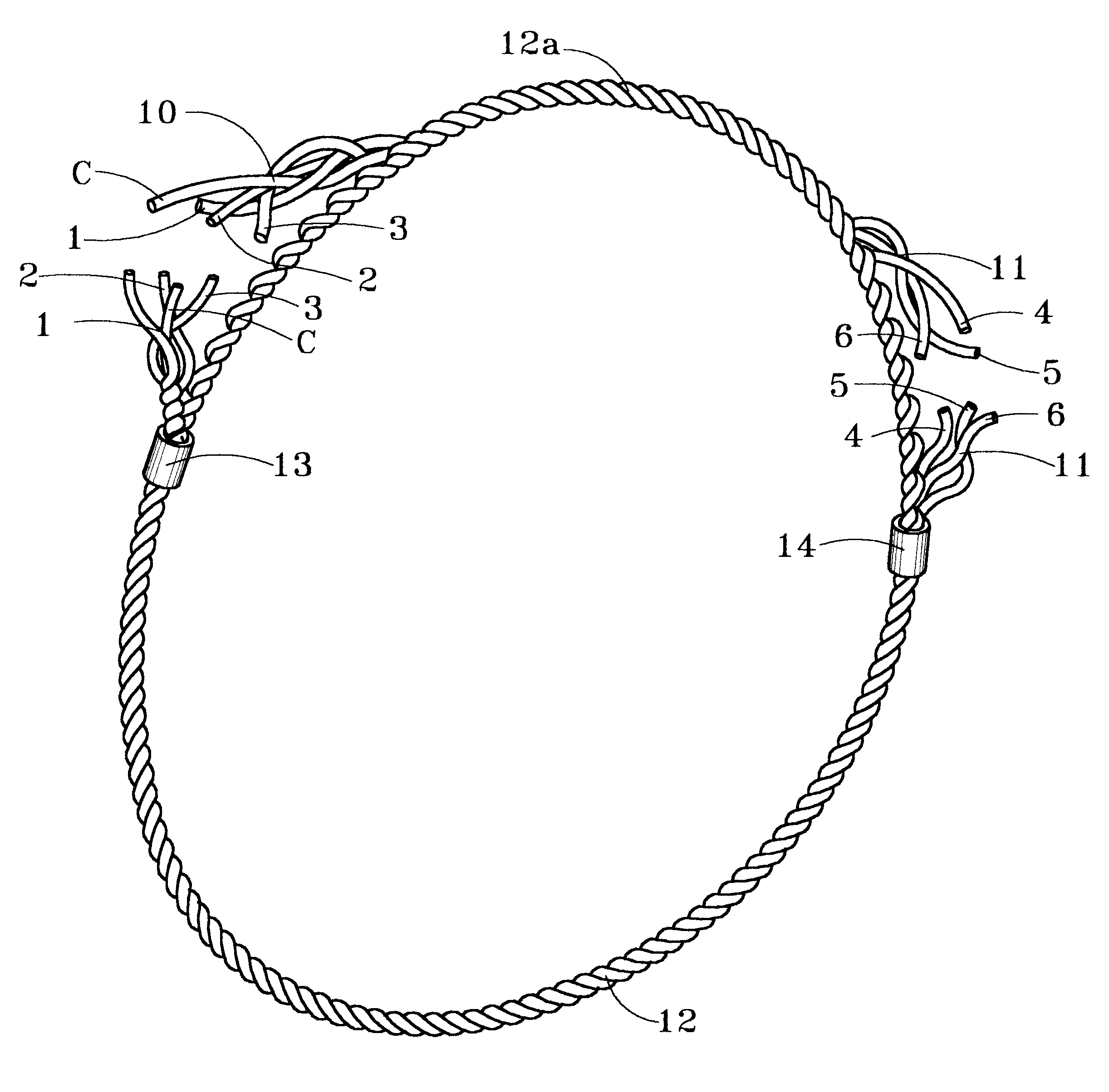
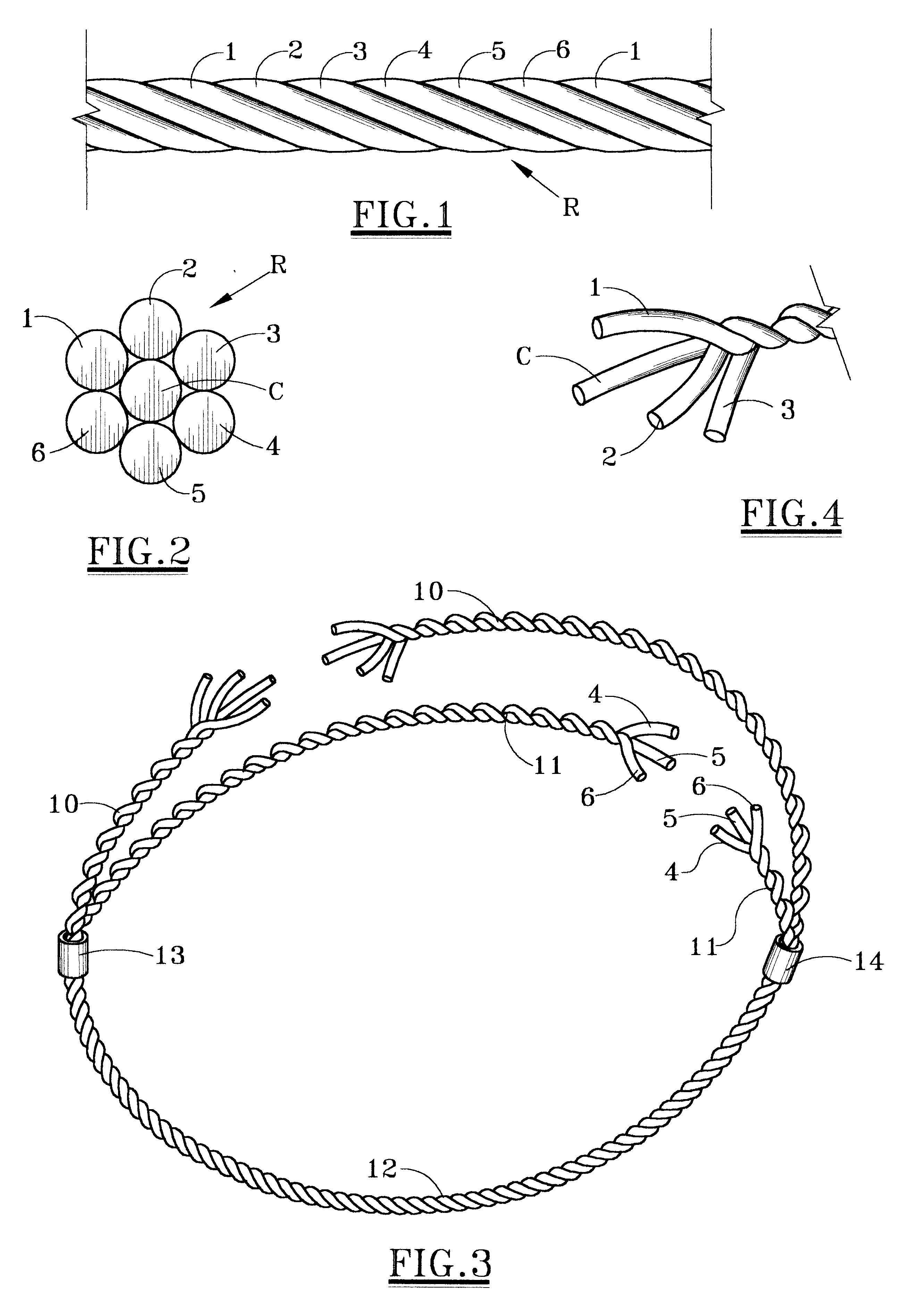
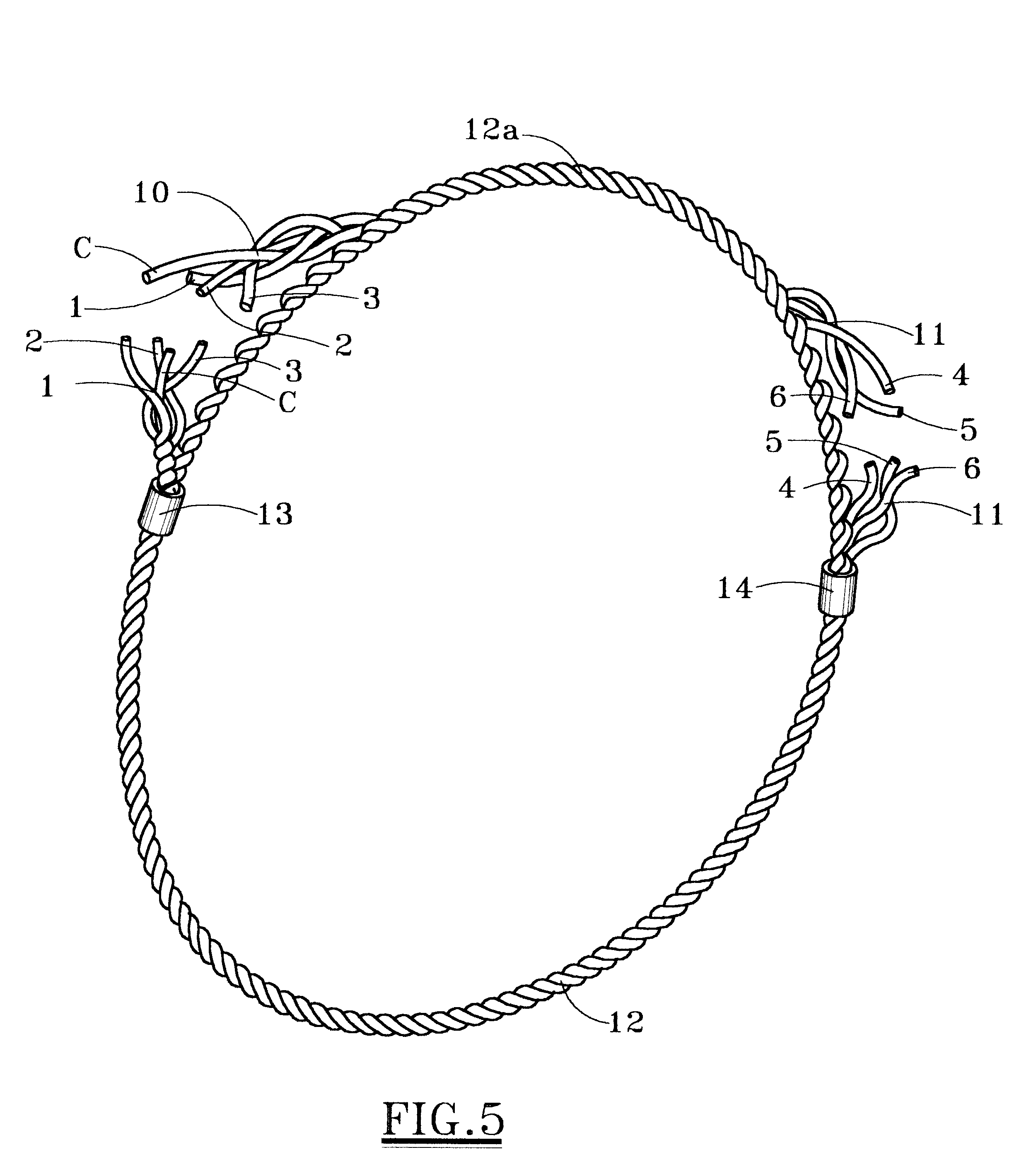
The present invention provides a wire rope sling and method of making the same in which the rope is cut a predetermined length to provide first and second ends of the core and wire strands. In a preferred embodiment, the rope comprises six strands of wire helically laid around a core. Three of the strands are separated from the core and the other three strands, shifted or displaced along side the core and other strands a predetermined amount and rewoven with the core and other strands of wire into a continuous loop, the first and second ends of the three strands meeting along a continuous section of the core and other strands, the first and second ends of the core and other strands meeting along a continuous section of the three strands. A first splicing sleeve surrounds the first and second ends of the three strands and the continuous section of core and other strands and a second splicing sleeve surrounds the first and second ends of the core and other strands and continuous section of the three strands in a tightly gripping manner. The circular sling or grommet constructed in this manner provides a relatively low cost, low headroom sling with greater lifting capacity than any of the prior art. Utilizing working load limit charts, correct pins and connecting points can be determined without guess work. The unique design of the sling of the present invention results in a shorter sling of greater capacity and better load control. Many other objects and advantages of the invention will be apparent from reading the description which follows in conjunction with the accompanying drawings.

Problems solved by technology

This style of a sling does not have a splice at all and is subject to catastrophic failure when the sleeves fail.
One of the problems in making and using slings of the prior art for large capacities is the increased length of the sling required by larger diameter wire rope.
Thus, large capacity slings cannot be fabricated in the prior art in such a way as to allow for very low headroom conditions.
Many times the headroom available for a large lift will not allow for the length needed.
Therefore, such high capacity, low head room situations, have to be addressed with link plates, shackles or other specially engineered, costly and heavy solutions.
Making numerous smaller lifts requires additional time, escalating the price of erection and / or removal of items being lifted.

Method used


Image

  • Wire rope sling and methods of making same
  • Wire rope sling and methods of making same
  • Wire rope sling and methods of making same

Examples


Embodiment Construction

Referring first to FIGS. 1 and 2, there is shown a section of wire rope R comprising a core C and six strands of wire 1, 2, 3, 4, 5, 6 helically laid around the core. The lay length of the rope is approximately equal to the distance between the two reference numerals "1" in FIG. 1. The core C can be made of any suitable material which provides proper support for the strands 1-6 under normal bending and loading conditions, e.g. fibers or steel. If steel, the core may consist of a strand or an independent wire rope.

The strands are made of two or more wires, laid in any one of many specific geometric arrangements, or any combination of steel wires with other materials such as natural or synthetic fibers. A strand can be made up of any number of wires and the wire rope can be made of any number of strands. However, a six strand wire rope is most commonly used for circular slings or grommets.

In initial steps of making the sling or grommet of the present invention, the wire rope R is cut ...


PUM


Abstract

A wire rope sling made of wire rope having a core and multiple strands of wire helically laid around the core and cut from a predetermined length. Approximately half of the strands of wire are separated from the core and the remaining strands of wire, shifted, relative to the core, a predetermined distance and rewoven with the core and remaining strands of wire into a continuous loop. A splicing sleeve surrounds first and second ends of the approximately half of the strands and a continuous section of the core and remaining strands in a tightly engaged manner and another splicing sleeve surrounds first and second ends of the core and the remaining strands and a continuous section of the approximately half of the strands in a tightly engaged manner.

Description

1. Field of the InventionThe present invention pertains to wire rope slings. More specifically, the present invention pertains to an improved circular wire rope sling or grommet and methods of making the same.2. Description of the Prior ArtWire rope consists of three basic components: (1) a core, (2) wires which form a strand and (3) multi-wire strands laid helically around the core. The wire can be made of any number of materials including steel, iron, stainless steel, monel and bronze. The most widely used material is high carbon steel. Strands are made up of two or more wires laid in any one of many specific geometric arrangements, or in combination of steel wires with some other material such as natural or synthetic fibers.The core of wire rope is made of materials which will provide proper support for the strands helically laid therearound under normal bending and loading conditions. Core materials include fibers (hard vegetable or synthetic) or steel. A steel core may consist ...

Claims


Application Information

Patent Timeline
Patent Type & Authority Patents(United States)
IPC IPC(8): B66C1/12
CPCB66C1/12D07B7/167D07B7/165Y10T24/3909D07B7/169
Inventor BROWN, RANDALL B.MCCARTHY, CHARLES L.
Owner HOLLOWAY HOUSTON
Learn More