Fiber optic cables with strength members and methods of making the same

a technology of fiber optic cables and strength members, applied in the direction of optics, fibre mechanical structures, instruments, etc., can solve the problems of increasing cable manufacturing costs, shortening fiber optic cable materials, and high cost of aramid fibers

Inactive Publication Date: 2002-05-14
CORNING OPTICAL COMM LLC
View PDF42 Cites 119 Cited by
  • Summary
  • Abstract
  • Description
  • Claims
  • Application Information

AI Technical Summary

Benefits of technology

A still further aspect of the present invention includes a method of manufacturing a fiber optic cable. The method includes paying off at least one optical fiber component and at least one strength member. The at least one strength member includes at least one yarn. The yarn includes a coating system having a percentage by weight, based on the dry weight of the yarn, of about 2.0% or less. A cable core defined by placing the at least one strength member adjacent to the at least one optical fiber component. The method also includes extruding a jacket around the cable core. Additionally, the method of manufacture can include a tube-on extrusion process that may provide a space at the time of extrusion.

Problems solved by technology

This demand for fiber optic cables has led to shortages of fiber optic cable materials.
Aramid fibers can, however, be expensive.
This cable can be made of flame retardant materials for riser or plenum applications; however, the cable has disadvantages.
For example, the cable requires a significant amount of aramid fibers that are typically expensive, thereby increasing cable manufacturing costs.
Although this fiber optic cable is designed to prevent attenuation induced during the manufacturing process, this design has several disadvantages.
For example, the cable requires a significant amount of aramid fibers, which if available, are expensive and increase cable manufacturing costs.
Conventional glass components have been developed for outdoor fiber optic cables but have had limited application in premises fiber optic cables.
Consequently, when conventional glass components were employed in fiber optic cables having 50 / 125 .mu.m tight buffered optical fibers, testing revealed unacceptably high levels of attenuation.
The unacceptable characteristics are believed to be due to the fact that conventional glass components are relatively hard and stiff when compared with aramid fibers of the same size.

Method used


Image

  • Fiber optic cables with strength members and methods of making the same
  • Fiber optic cables with strength members and methods of making the same
  • Fiber optic cables with strength members and methods of making the same

Examples


Embodiment Construction

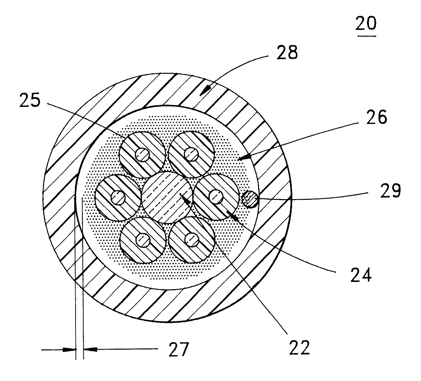
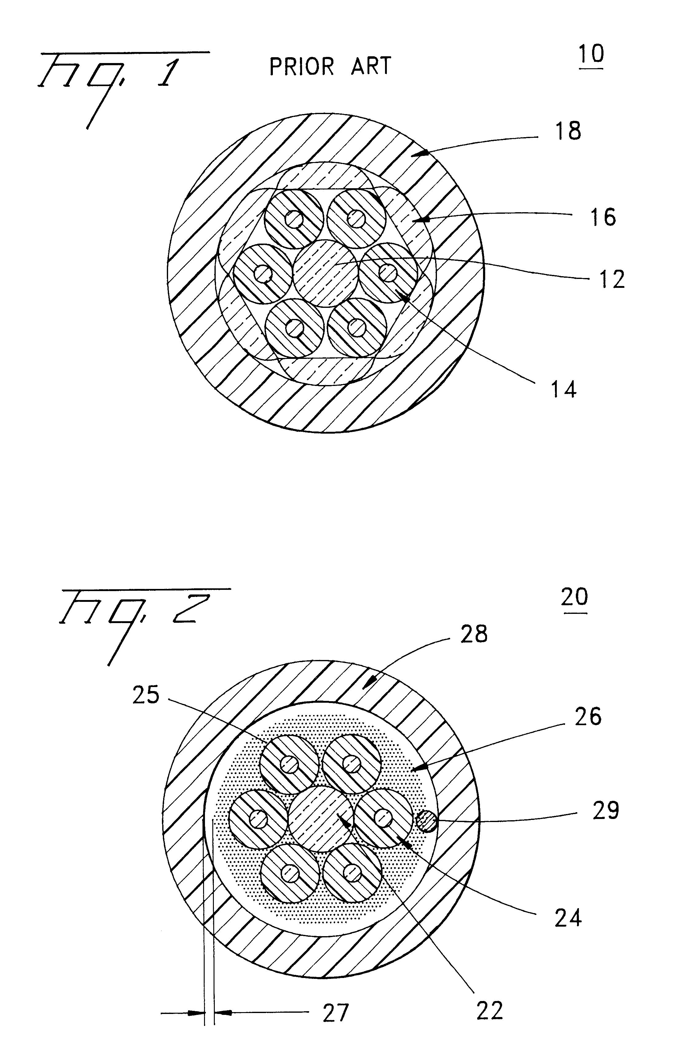
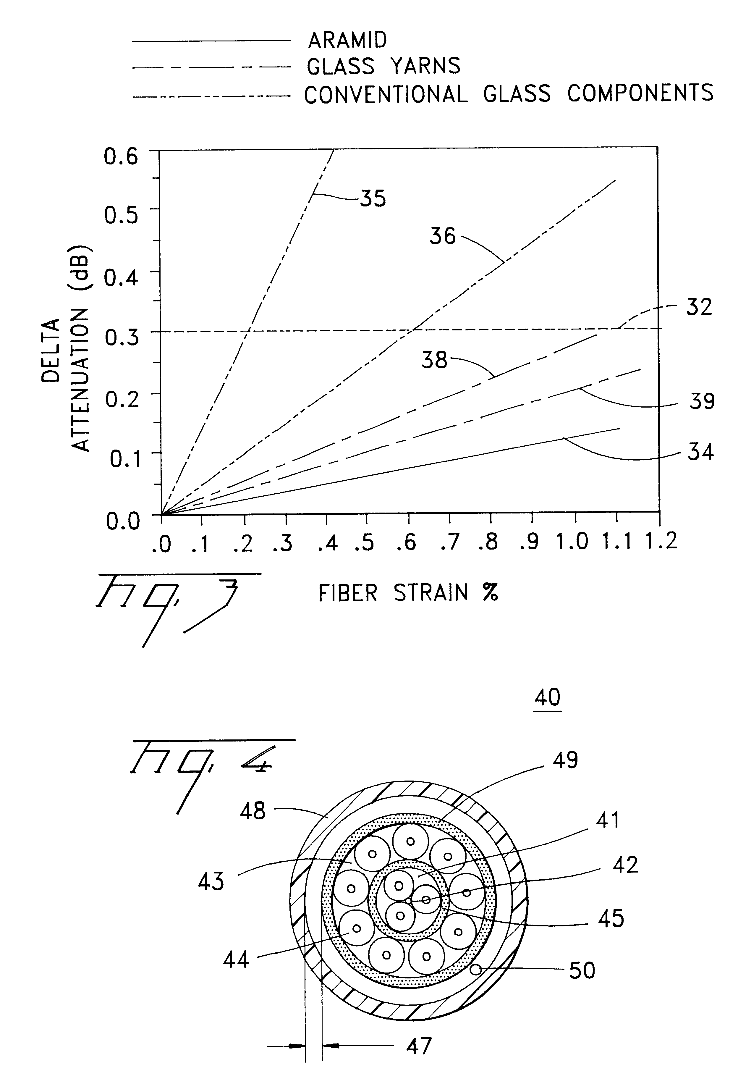
A fiber optic cable 20 according to an embodiment of the present invention is depicted in FIG. 2. Fiber optic cable 20 includes a plurality of optical fiber components 24 that are stranded or longitudinally disposed about a central member 22. Interposed between optical fiber components 24 and a jacket 28 is a layer 25 of stranded yarns 26 substantially surrounding optical fiber components 24. The present invention can include a space 27, at the time of extrusion, disposed between a cable core 80 and a jacket 28 allowing relative movement among layer 25, yarns 26, optical fiber components 24 and jacket 28, for example, during cable bending and / or thermal variation.

Yarns used in cables according to the present invention are softer and have increased flexibility compared with the conventional glass components used in previous outdoor fiber optic cables. Yarns 26 of the present invention are substantially not conventional glass components, but, rather can include similar glass compositi...


PUM


Abstract

A fiber optic cable and method of manufacturing the same include at least one optical fiber component and at least one strength member disposed adjacent to said at least one optical fiber component. The at least one strength member includes a yarn and a jacket generally surrounding said at least one optical fiber component and said at least one strength member. The yarn includes a coating system having a percentage by weight, based on the dry weight of said yarn, of about 2.0% or less. Other embodiments can include a delta attenuation of about 0.3 dB or less over the range of about 0% to about 1.0% of optical fiber strain, a peak cable core pull-out force of about 1 newton or less, or a space disposed between a cable core and the jacket.

Description

The present invention relates generally to fiber optic cables and, more particularly, to fiber optic cables having at least one strength member.Fiber optic cables include optical fibers that are capable of transmitting voice, video, and data signals. Fiber optic cables have advantages over electrical voice, video and data signal carriers, for example, increased data capacity. As businesses and households demand increased data capacity, fiber optic cables can eventually displace electrical voice, video, and data signal carriers. This demand for fiber optic cables has led to shortages of fiber optic cable materials.Aramid fibers are cable materials that can serve several functions, such as: providing tensile strength to the fiber optic cable; cushioning the optical fibers from compression and impact loads; covering the optical fibers during the extrusion of the outer jacket to prevent the optical fibers from sticking to the extruded outer jacket; and binding the optical fibers togethe...

Claims


Application Information

Patent Timeline
Patent Type & Authority Patents(United States)
IPC IPC(8): G02B6/44
CPCG02B6/4432G02B6/4486
Inventor HURLEY, WILLIAM C.
Owner CORNING OPTICAL COMM LLC
Why Eureka
Try Eureka