Hinge with electrical wiring

a technology of electrical wiring and hinges, applied in the field of hinges with electrical wiring, can solve the problems of uneven opening and closing of doors, weakening gears, etc., and achieve the effects of reducing wear and tear, facilitating wiring passage, and less exposure of wiring

Active Publication Date: 2012-11-13
SELECT PRODS
View PDF22 Cites 14 Cited by
  • Summary
  • Abstract
  • Description
  • Claims
  • Application Information

AI Technical Summary

Benefits of technology

[0005]The present invention differs from the prior art by passing electric wiring enclosed in a flexible tube through channels under the leaves and a hole in a thrust bearing employed in the hinge. The Pemko product passes electric wiring enclosed in a flat, flexible cable through a cutout in the gears employed in the hinge. This arrangement weakens the gears at the point where the cutout occurs. The Pemko design also employs a taller cap than that employed in the present invention to cover the cable and the gears, apparently to provide space for the cable. The taller cap prevents the door on which the Pemko hinge is installed from opening more than 150 degrees. In contrast the tube containing wiring in the present invention passes through a hole in a thrust bearing employed in the hinge. This arrangement permits the use of a cap with a lower profile that in turn allows a door on which the present invention is installed to open a full 180 degrees. The use of a flexible tube to enclose the wiring facilitates the passage of wiring through the hole in the bearing. Less exposure of the wiring also reduces wear and tear as well as the possibility of tampering. The character and advantages of the present invention will become more apparent in the following more detailed description.
[0006]The present invention consists essentially of a combination for providing a conduit for electrical wiring through a geared full surface continuous hinge adapted for attachment to the outside surfaces of a door and a frame in which the door is mounted. The combination comprises a door leaf and a frame leaf, each leaf having a plate segment and a plurality of geared segments interrupted by thrust bearing segments. The leaves are adapted to pivot around said bearings and meshed geared segments. More specifically the combination comprises (a) at least one thrust bearing having a hole aligned with holes in and channels under the hinge leaf plates, said holes and channels being large enough to allow a flexible tube containing electrical wires to pass sequentially into a first or outer round hole in the frame leaf plate, through the channel under that plate, out a second or inner oval hole in the frame leaf plate, through the hole in the thrust bearing, through a first or inner oval hole in the door leaf plate, through the channel under a door leaf plate and out a second or outer round hole in the door leaf plate, (b) a cap covering and holding the gears and bearings portions of the hinge together and extending for substantially the full length of the hinge and (c) covers extending for substantially the full length of the hinge over the first hole in frame leaf plate and the second hole of the door leaf plate. The covers over the leaf plates also cover the holes through which screws or bolts attach the leaves to the frame and door surfaces. Thus the wiring assembly is both substantially concealed and protected as it passes through the hinge without interfering with a full 180 degree operation of the door on which the hinge is attached. When the holes in the plates and wires are covered, they are also more secure and less subject to tampering, especially important when appliances in a door are designed to make the doors less accessible to unauthorized personnel.

Problems solved by technology

Eventually heavy doors and heavy usage combine to cause the screws used to connect the small widely separated leaves of butt hinges to loosen and cause the doors to sag and close unevenly.
This arrangement weakens the gears at the point where the cutout occurs.

Method used


Image

  • Hinge with electrical wiring
  • Hinge with electrical wiring
  • Hinge with electrical wiring

Examples


Embodiment Construction

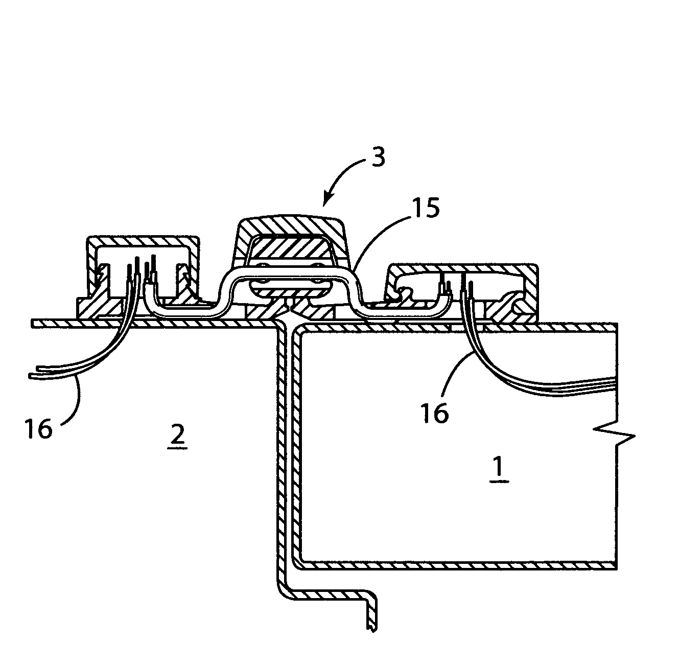
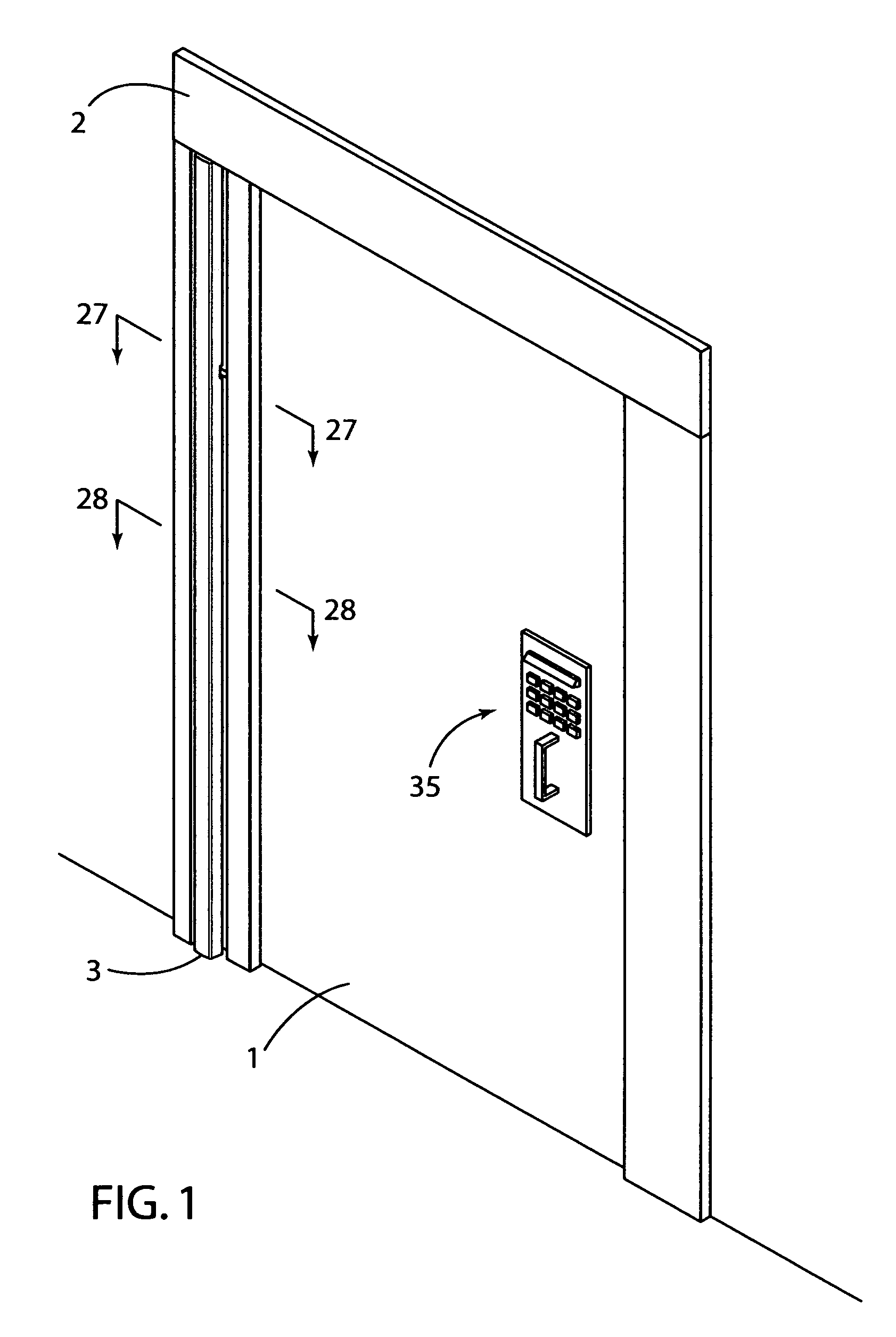
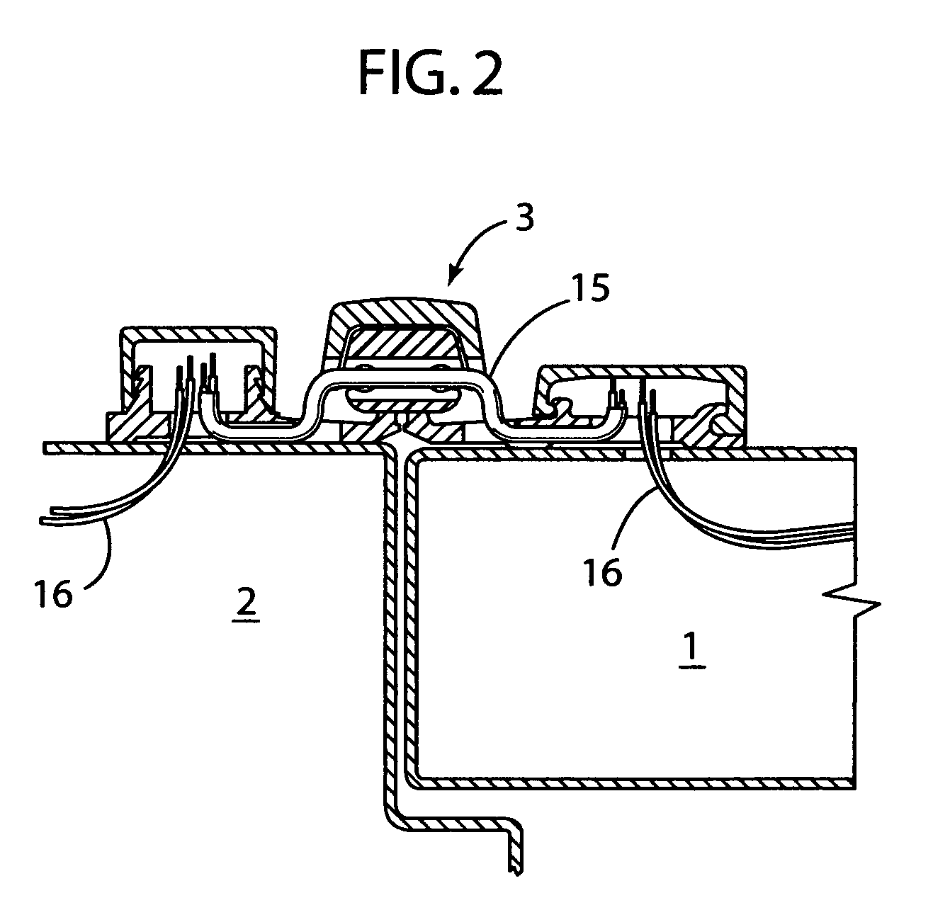
[0054]The preferred embodiments of the present invention consist of the following components as more clearly shown in FIGS. 1-13:[0055](1) A full surface mount type geared aluminum or equivalent continuous door hinge 3 of any length.[0056](2) From one to 15 strands of 22 gauge flexible wire 16 in lengths of from 5 to 36 inches.[0057](3) From at least 1 to about 3 modified thrust bearings 9.[0058](4) PVC or equivalent flexible tubing 15 in a diameter suitable to pass through a hole 10 in the modified thrust bearings 9.[0059](5) A gear cap 17 to cover the meshed gears 8 and bearings 9,31 and two covers 18,19 to cover the machined holes 11,13,25,26 in the plates 6,7 of the leaves 4,5.[0060]The essential equipment required to convert an ordinary geared continuous full surface hinge into the above embodiments include:[0061](1) A machine tool capable of repeatedly machining precision holes, channels and the like.[0062](2) Tooling capable of machining metals.[0063](3) Work holding fixtures...


PUM


Abstract

A geared full surface mounted continuous hinge with a hole in a thrust bearing supporting the hinge, said hole adapted to accommodate a flexible tube containing electrical wiring and thereby facilitate the passage of electric current from a frame to appliances in a door connected to the frame using the hinge.

Description

[0001]This application claims the benefit under 34 U.S.C. 119(e) of provisional application No. 61 / 074,855 filed Jun. 23, 2008 entitled “SURFACE MOUNTED GEAR HINGE WITH ELECTRICAL WIRING”.BACKGROUND OF THE INVENTION[0002]Many buildings are equipped with doors that require transfer of electric power from the door frame to locks, latches, panic devices, alarms, cameras, I.D. readers and the like mounted on or in the door. The prior art provides examples of transfer of electrical power through knuckle hinges (hereinafter referred to as butt hinges) such as those described in U.S. Pat. Nos. 3,838,234; 3,84286; and 4,412,711. U.S. Pat. No. 7,063,042 provides an example of electrical transfer through a continuous gear butt hinge, not a surface mounted hinge.[0003]A butt hinge is largely hidden from view when a door employing the hinge is closed. In contrast a surface mounted hinge is almost fully visible. An example of electrical transfer through a surface mounted continuous gear hinge ca...

Claims


Application Information

Patent Timeline
Patent Type & Authority Patents(United States)
IPC IPC(8): E05D7/00
CPCE05D3/122E05D7/009E05D11/0081Y10T16/533E05Y2900/132Y10T16/541
Inventor SCHAU, TIMOTHY ALAN
Owner SELECT PRODS
Why Eureka
Try Eureka