Method for making a motor car body

Inactive Publication Date: 2002-05-21
ABB BODY & WHITE
View PDF13 Cites 68 Cited by
  • Summary
  • Abstract
  • Description
  • Claims
  • Application Information

AI Technical Summary

Benefits of technology

The present invention stems from the observation whereby the greatest difficulty in setting up the shape of motor vehicle bodywork lies at the end of the underbody remote from the engine compartment, i.e. a location where the underbody is itself relatively deformable. In contrast, beside the engine compartment of the underbody

Problems solved by technology

The major drawback of such welding stations lies in the considerable weight and size of the tooling for holding the bodywork in shape, which tooling firstly obstructs access for the welding robots and secondly, and above all, requires handlin

Method used


Image

  • Method for making a motor car body
  • Method for making a motor car body
  • Method for making a motor car body

Examples


Embodiment Construction

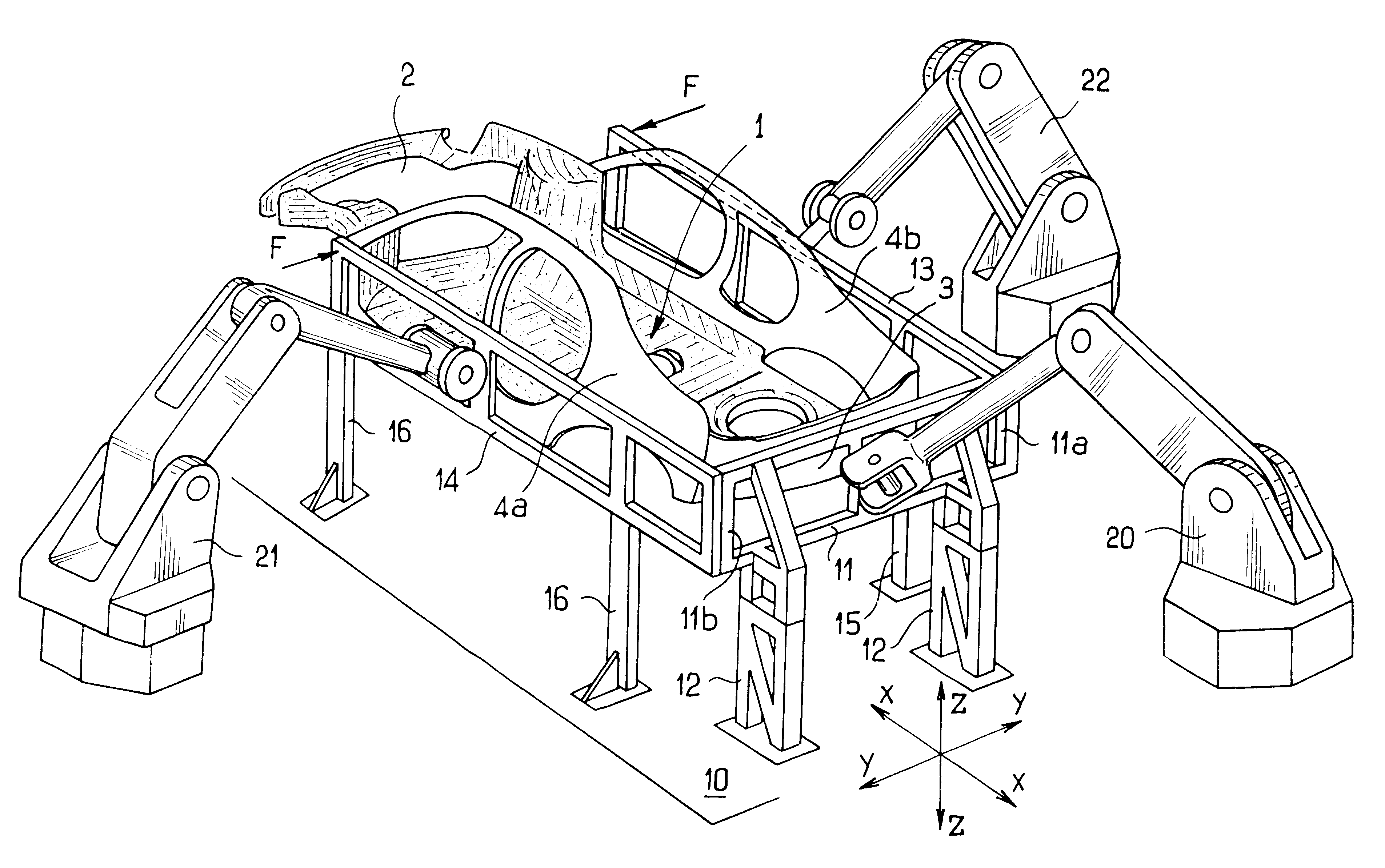
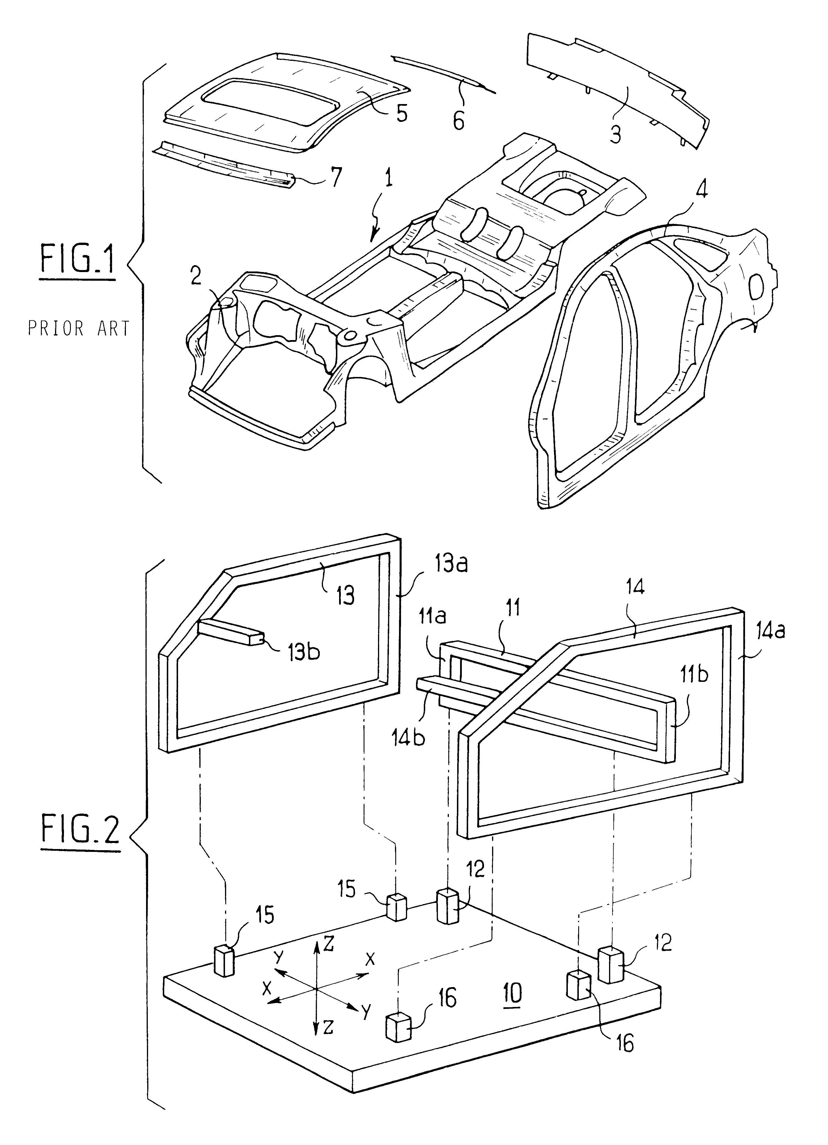
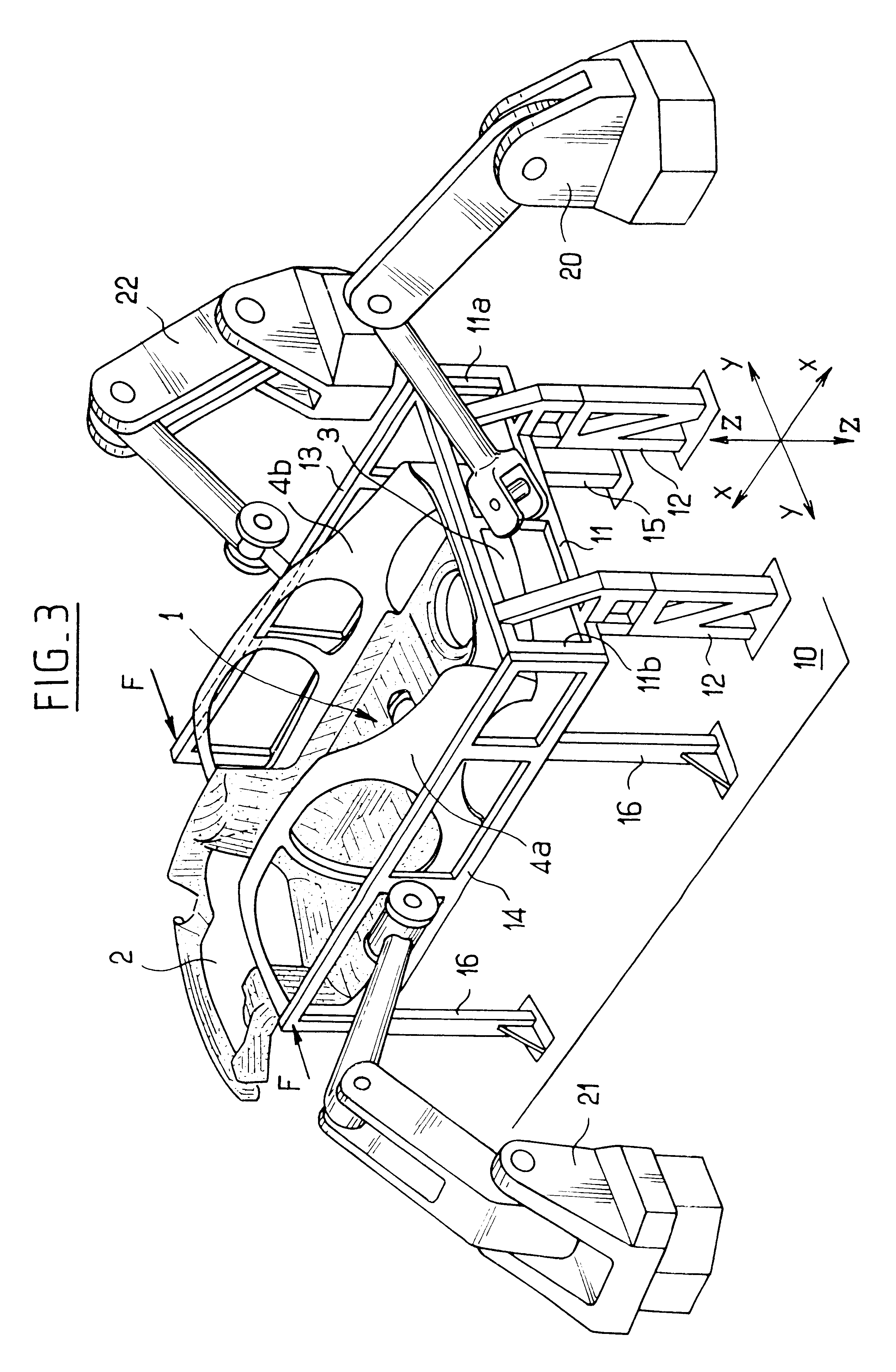
FIG. 2 shows a fixed structure 10 of a station for assembling vehicle bodywork and possessing a frame of reference X, Y, Z. A support for the underbody 1 of a motor vehicle body can be brought into the structure. The means for bringing in the support and putting it into the position in the X, Y, Z frame of reference are known per se and they are not shown. For example, the support can be constituted by a pallet which travels by means of a conveyor passing through the structure 10 along the X direction, lifting means being provided in the structure to separate the pallet from the conveyor and to put it in a reference position in the X, Y, Z frame of reference. A tool that is transverse in the meaning of the invention is represented in the form of a frame 11 extending transversely to the X direction and suitable for being coupled to the structure 10, e.g. via support studs 12, these studs and the frame 11 being provided with means for co-operating so as to ensure that the frame 11 is ...


PUM


Abstract

A method of making car bodywork, the method including a step of assembling body sides (4a, 4b) to an underbody (1), the underbody (1) including a rigid engine compartment (2) at one end and being placed in an assembly station in a precise position determined in an orthogonal frame of reference having directions X, Y, and Z, the method consisting: in putting the body sides (4a, 4b) into position and holding them in position in the frame of reference of the station by means of two parallel tools (13, 14) each co-operating with a respective body side (4a, 4b), and at least one transverse tool (11) extending transversely to said parallel tools, the three tools being connected to one another and to the X, Y, Z frame of reference of the station in such a manner that the transverse tool (11) is placed and held in a position that is precise and locked in the frame of reference and that it forms a spacer and bracing tool in the Y direction for the two parallel tools (13, 14) in a zone that is remote from the engine compartment (2) of the underbody (1); and in maintaining a force (F) pressing each of the parallel tools (13, 14) at least against the sides of the engine compartment (2) of the underbody (1) while the body sides are being assembled to the underbody.

Description

This application is the national phase under 35 U.S.C. .sctn.371 of PCT International Application No. PCT / FR99 / 01280 which has an International filing date of Jun. 1, 1999, which designated the United States of America.The present invention relates to a method of making car bodywork, the method enabling the tooling used in assembly stations to be as lightweight as possible so as to enable robots to be used as the tools for setting up the bodywork in a welding station and / or the tools for handling bodywork subassemblies that are to be assembled together.In present assembly lines for assembling car bodywork, the subassemblies are positioned relative to one another and relative to the welding robots by means of tooling that is rigid and heavy. By their very nature, bodywork pieces are deformable when subjected to stresses and the tooling used for making bodywork of determined and reproducible shape performs two functions: firstly it constitutes reinforcement for each deformable subasse...

Claims


Application Information

Patent Timeline
IPC IPC(8): B62D65/00B62D65/02
CPCB62D65/00Y10T29/53961Y10T29/49622Y10T29/49998Y10T29/53983Y10T29/49899
Inventor MALATIER, FRAN.CEDILLA.OIS
Owner ABB BODY & WHITE
Why Eureka
Try Eureka