Method and device for the controlled break-up of liquid jets

a technology of liquid jets and controlled breakage, which is applied in the field of controlled breakage of liquid jets, can solve the problems of high construction, operating and maintenance costs, and difficult implementation, and achieves the effects of reducing construction costs, reducing construction efficiency, and reducing production costs

Inactive Publication Date: 2002-05-21
UREA CASALE SA
View PDF5 Cites 0 Cited by
  • Summary
  • Abstract
  • Description
  • Claims
  • Application Information

AI Technical Summary

Benefits of technology

Advantageously, by means of the present invention it is possible to obtain substantially monodispersed drops by feeding the liquid for formation of the second jets under stationary conditions and at the same time causing variation in an appropriate manner of the pressure of this liquid.

Problems solved by technology

However, the above mentioned methods display a series of drawbacks, the first of which is that they are difficult to implement and unreliable.
Indeed, to be effectively implemented, these methods necessitate sophisticated equipment complicated to manufacture and requiring constant maintenance.
Consequently, to appropriately control the break-up of the liquid jets, high construction, operating and maintenance costs are necessary.
In addition, because of their complexity, mainly due to the need to provide means of transmission of acoustical or mechanical vibrations, the equipment for implementation of the methods according to the prior art cannot ensure obtaining substantially monodispersed drops in a constant manner over time.

Method used


Image

  • Method and device for the controlled break-up of liquid jets
  • Method and device for the controlled break-up of liquid jets
  • Method and device for the controlled break-up of liquid jets

Examples


Embodiment Construction

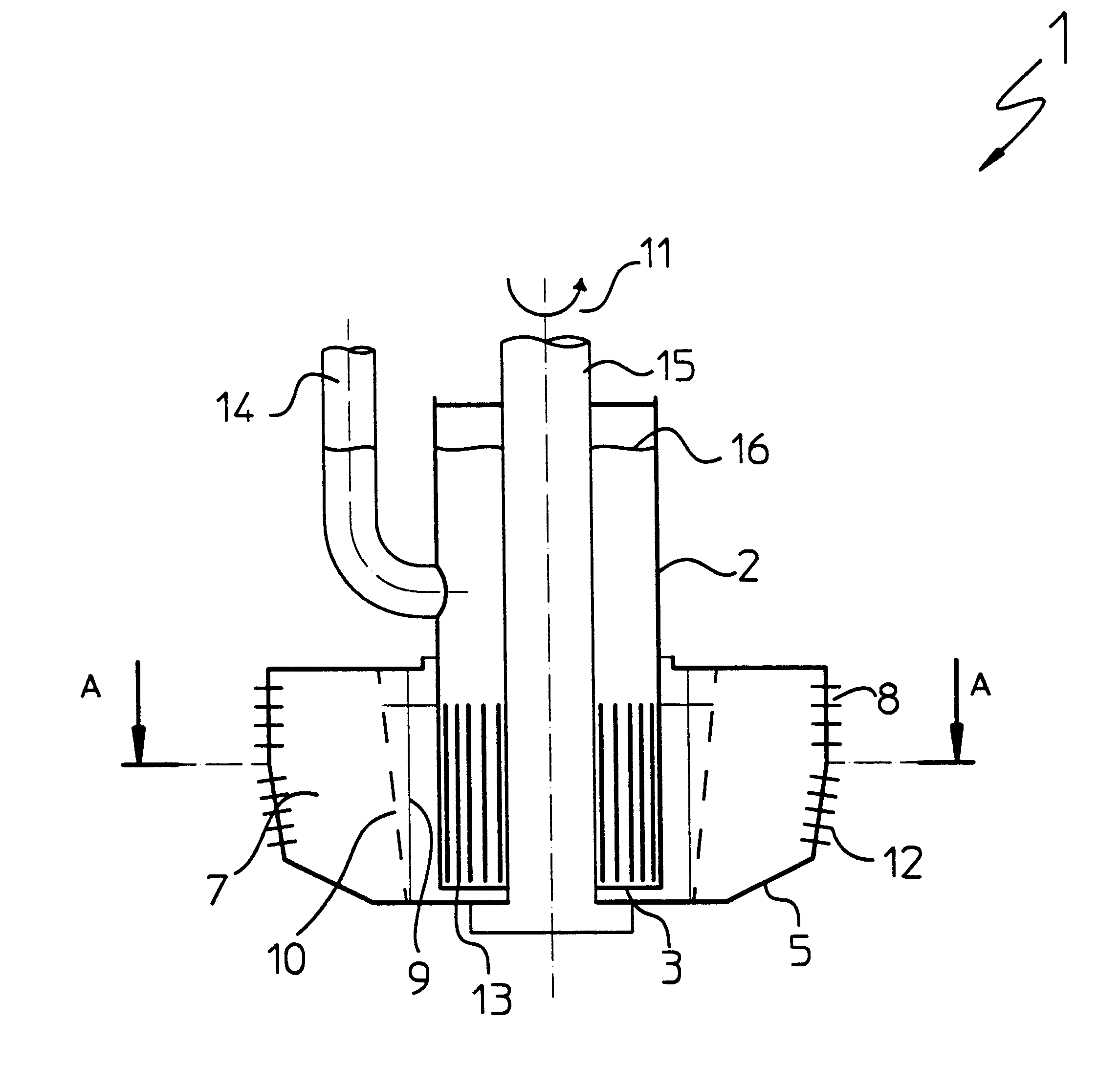
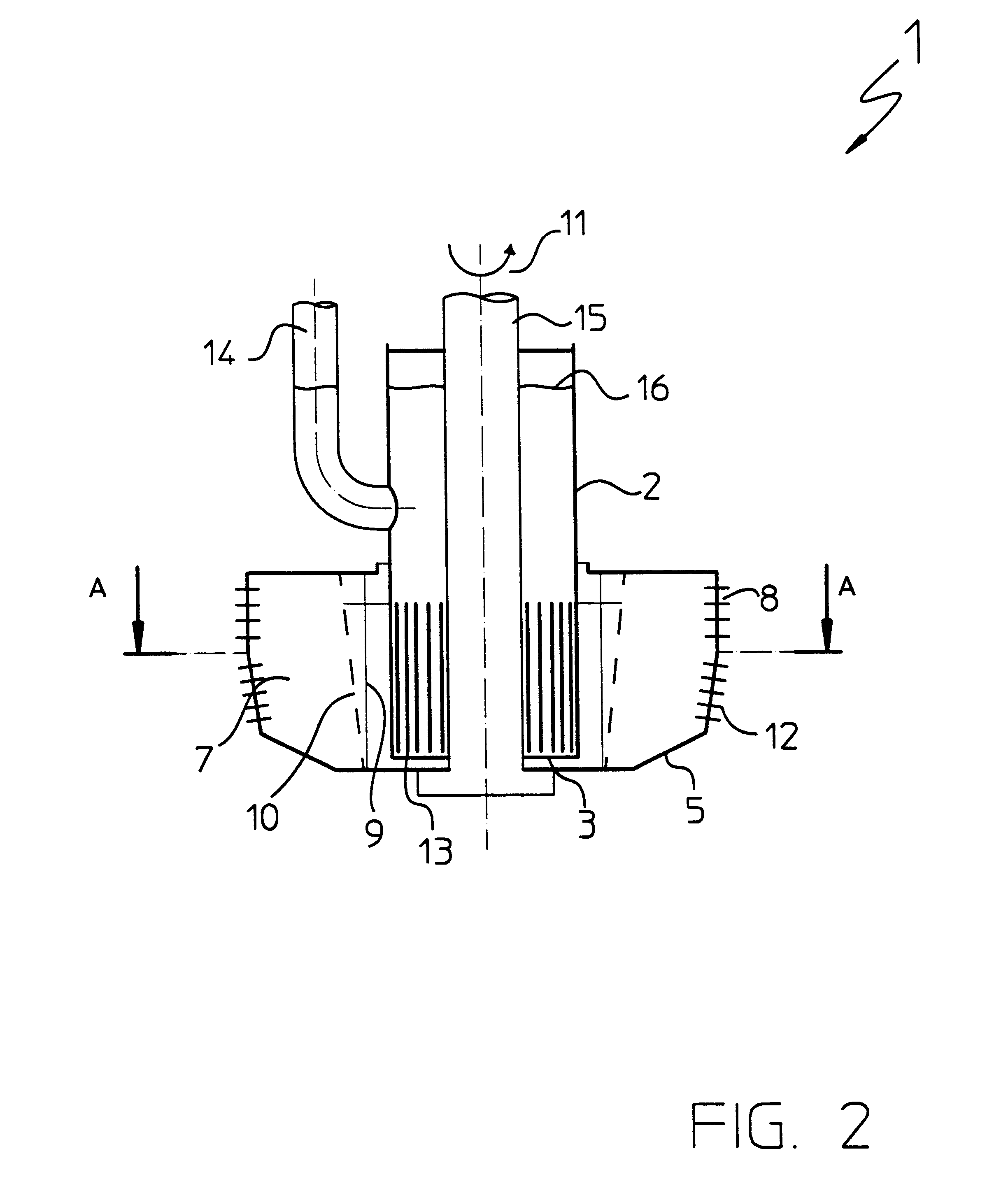
With reference to FIGS. 1 to 4, reference number 1 indicates as a whole a device for the controlled break-up of liquid jets according to the present invention especially suited for prilling of melted material, e.g. melted urea, for fertilizer production.

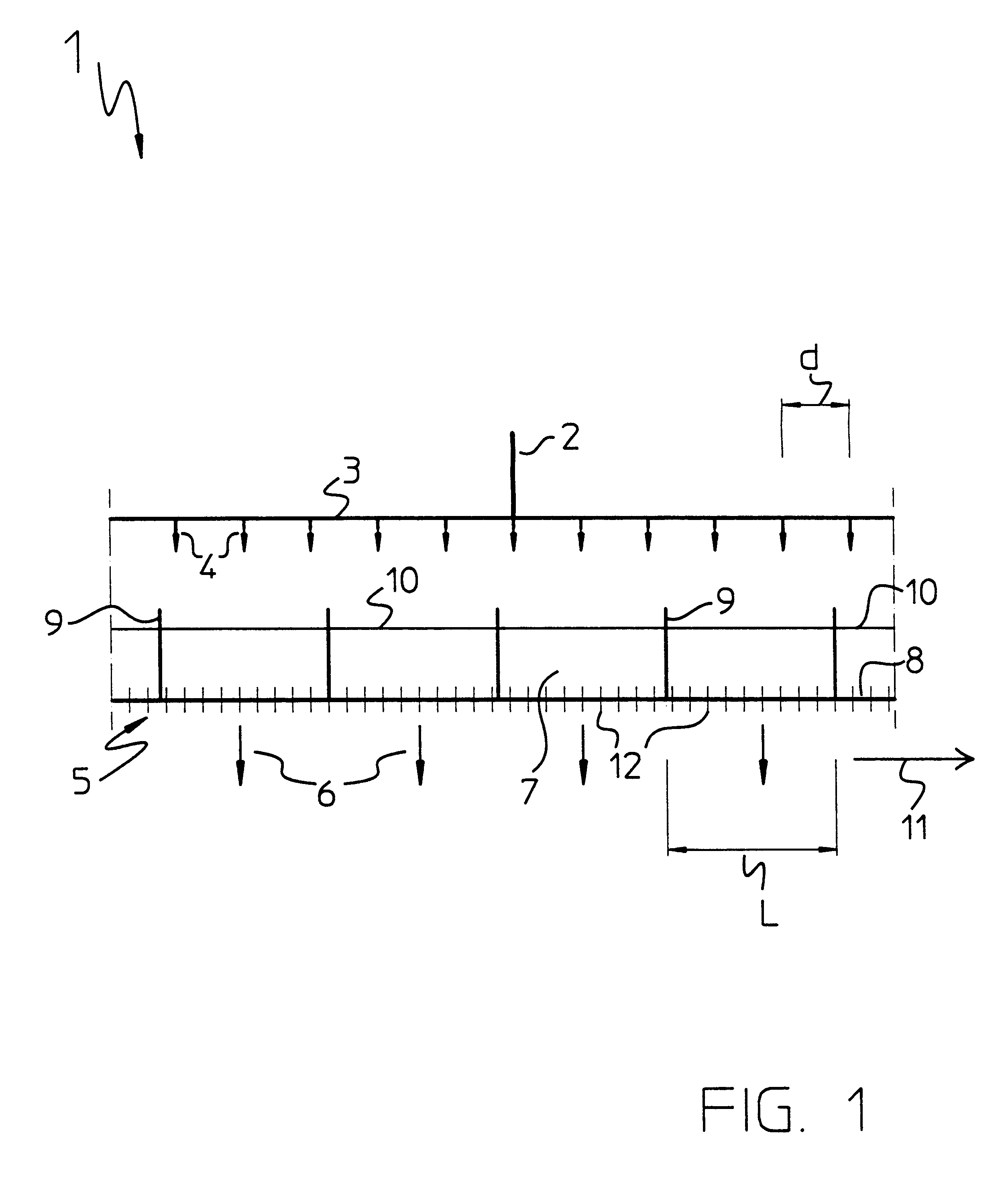
FIG. 1 shows schematically only a detail of the device 1 for the controlled break-up of the liquid jet to better point out the principles of the method according to the present invention.

The device 1 comprises a first liquid distributor 2 comprising a perforated wall 3 for delivery of a plurality of first liquid jets 4 having stationary motion.

Preferably, these jets 4 are delivered by respective openings in the perforated wall 3 arranged in substantially parallel rows and extending longitudinally for a predetermined section of the distributor 2 in the direction normal to the plane of FIG. 1.

As an alternative, the openings in the perforated wall 3 consist of a plurality of substantially parallel longitudinal slits also extending in a ...


PUM

PropertyMeasurementUnit
pressureaaaaaaaaaa
densityaaaaaaaaaa
frequencyaaaaaaaaaa

Abstract

A method for the controlled break-up of liquid jets for production of substantially monodispersed drops stands out for the fact that it comprises the steps of:feeding a plurality of first liquid jets (4) having stationary motion to a plurality of mutually independent sectors and defined in a perforated surface (8);forming a head of liquid (10) in said sectors (7) near said perforated surface (8);causing said liquid to flow across said perforated surface (8) to form a plurality of second liquid jets (6);periodically changing with a predetermined frequency the momentum of the liquid fed to a predetermined sector (7) so as to impart to the liquid present in said sector a disturbance of predetermined magnitude consisting of a periodic change in the pressure near said perforated surface (8) which is transmitted to the second liquid jets (6) causing their controlled break-up in a plurality of substantially monodispersed drops.

Description

DESCRIPTION1. Field of ApplicationThe present invention relates to a method for the controlled break-up of liquid jets for the production of substantially monodispersed drops.In the following description and the subsequent claims, with the term: `substantially monodispersed drops`, it is intended to mean essentially spherical drops of liquid of substantially identical diameter.The present invention also relates to a device for implementation of the above mentioned method.As known, in the field of prilling of melted materials in more or less viscous liquid form, e.g. for the production of fertilizers, the requirement to provide a method of controlled break-up of liquid jets which on the one hand would allow obtaining substantially monodispersed drops and on the other hand would be reliable, easy to implement and not requiring high energy consumption and operating costs is becoming more urgent.In the following description, with the term: `prilling`, it is intended to mean a process by...

Claims


Application Information

Patent Timeline
Patent Type & Authority Patents(United States)
IPC IPC(8): B01J2/02B05B3/02B05B3/10C05C9/00B05B1/02B05B3/14
CPCB01J2/02C05C9/005B05B3/1021
Inventor BEDETTI, GIANFRANCO
Owner UREA CASALE SA
Why Eureka
Try Eureka