Communication antenna and equipment

a technology of communication antennas and equipment, applied in the direction of antennas, antenna supports/mountings, radiating element structural forms, etc., can solve problems such as energy loss, and achieve the effect of increasing bandwidth and shielding against radiation

Inactive Publication Date: 2002-05-21
GANESHMOORTHY DAVID +2
View PDF6 Cites 59 Cited by
  • Summary
  • Abstract
  • Description
  • Claims
  • Application Information

AI Technical Summary

Benefits of technology

According to a second preferred version of the second aspect of the present invention or the first preferred version thereof the parasitic elements are disposed relative to the driven element to ...

Problems solved by technology

However some energy is lost as circular polaris...

Method used


Image

  • Communication antenna and equipment
  • Communication antenna and equipment

Examples


Embodiment Construction

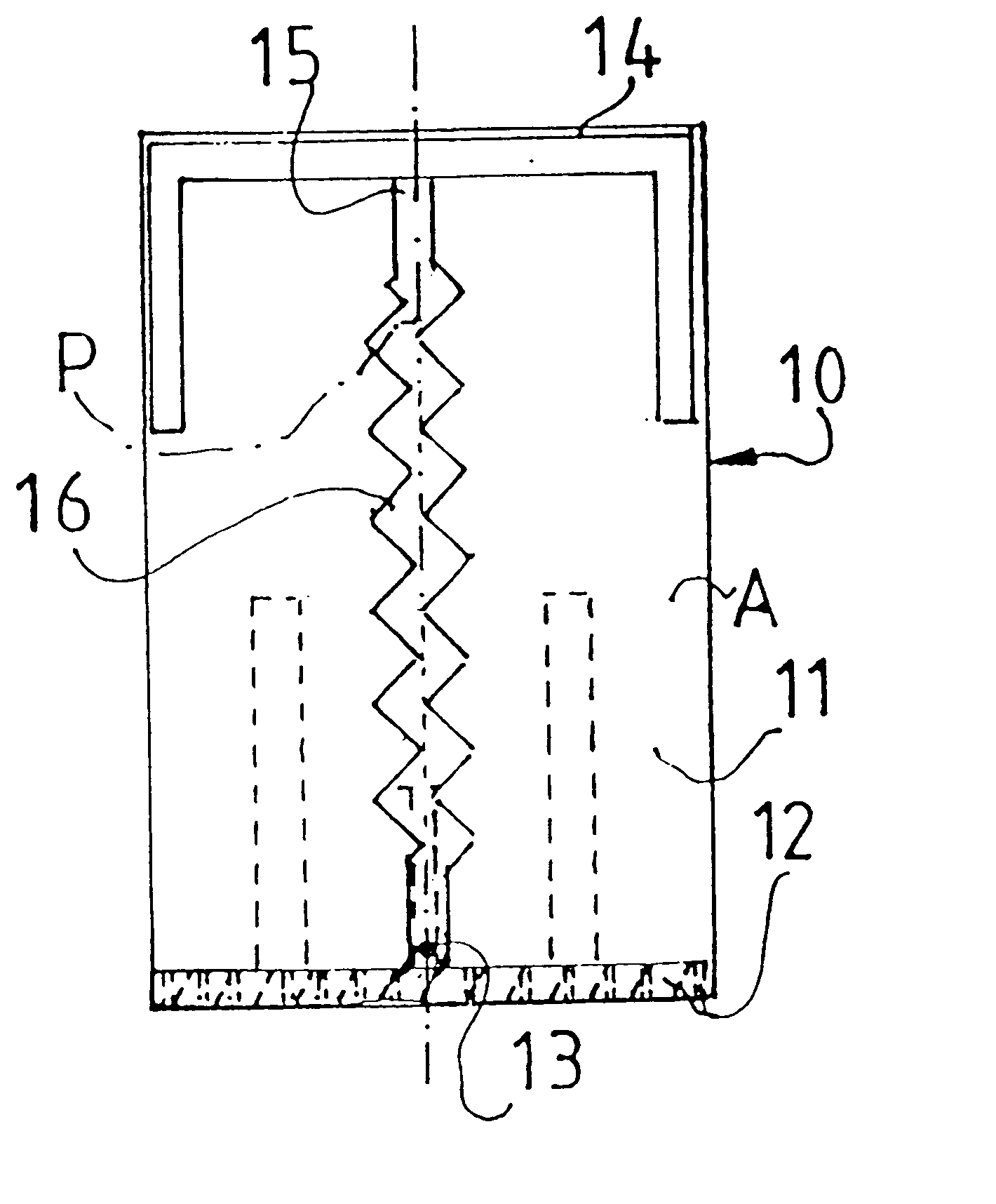
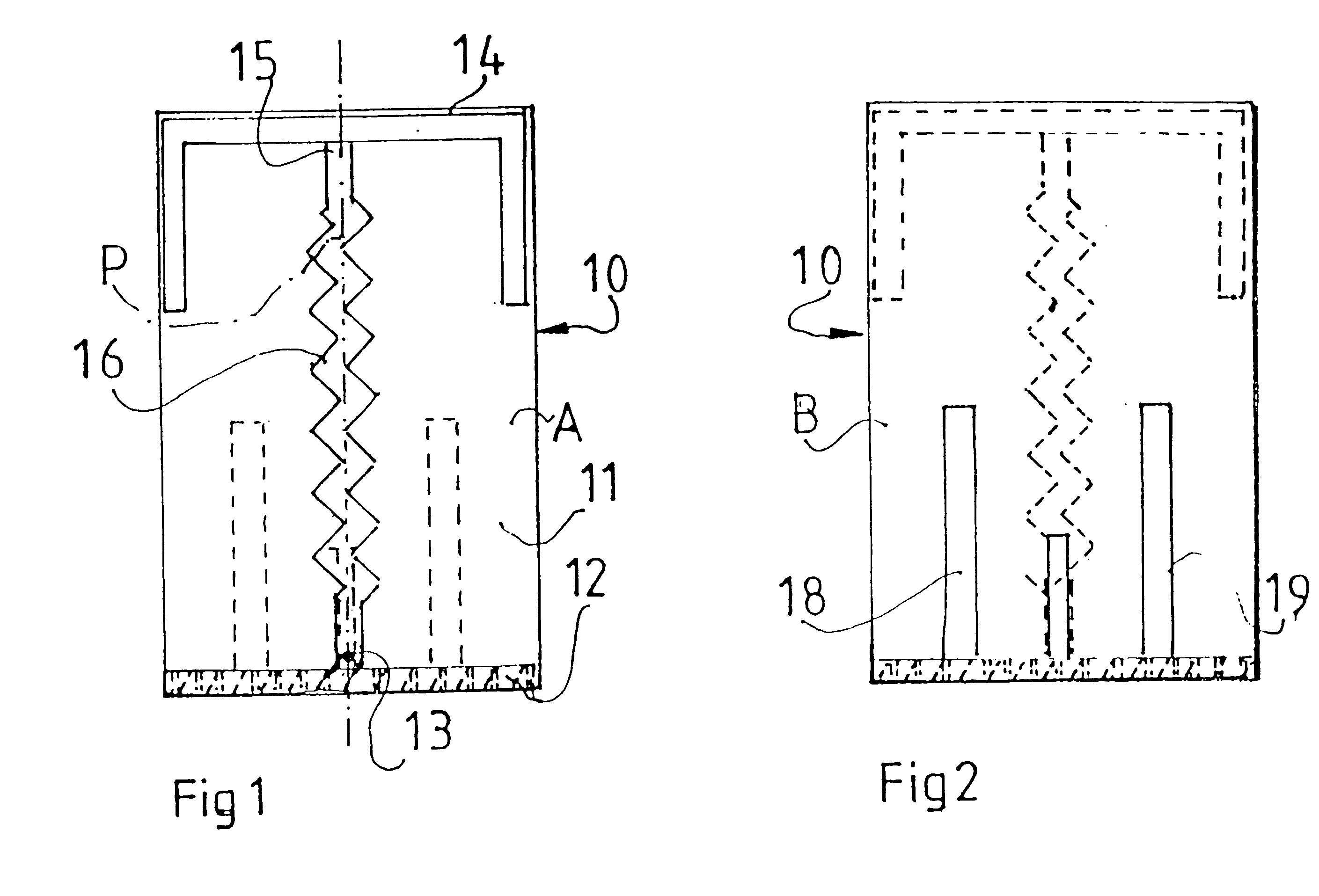
FIG. 1 shows an antenna 10 on a circuit board 11 located relative to a ground plane 12 which serves to locate a feed point 13. FIG. 1 shows side A of the circuit board 11 on which is deposited as an etched copper conductor: top loading element 14 providing an attachment point 15; and driven element 16 extending from feed point 13 to attachment point 15.

A straight path P extends from feed point 13 to attachment point 15. The driven element 16 follows a meandering path about path P. The length defined by the central locus of the meandering driven element 16 is longer than that of the path P. As shown in the drawings the driven element 16 is for most of its length in the form of a zigzag. In an alternative version the meandering path can be in the form of curved elements rather than angular ones. In other versions the driven element can be made up of a mixture of shapes so long as its overall length is greater than that of path length P. The actual length of the driven element 16 is de...


PUM


Abstract

A communication antenna (10) having a driven element (16) extending between a feed point (13) and an attachment point (15) to a top loaded element in which the driven element (16) is longer than the shortest distance (P) between the feed point (13) and the attachment point (15), the driven element (16) being configured to follow a meandering path between the feed point (13) and the attachment point (15). The driven element (16) is at least in part in the form of straight sections joined to give a zigzag configuration (16). Alternatively the driven element (16) is at least in part in the form of curved sections. At least a pair of parasitic elements (18, 19) can be provided with the members of the pair (18, 19) being disposed on opposite sides of, and off-set from, the driven element (16) and parallel to a straight ling (P) linking the feed point (13) to the attachment point (15); the parasitic elements (18, 19) serving to provide impedance matching and increased bandwidth and providing shielding against radiation from the antenna in a predetermined direction. Typically passive elements can be incorporated with the parasitic elements (18, 19) to provide for the overall reduction in the size of the antenna (10.

Description

This invention relates to a communication antenna and in particular it is concerned with a communication antenna for a mobile phone.Known antenna for a mobile phone consist of a helix with or without a radiating straight element. The helix serves to provide for radial radiation / reception. However some energy is lost as circular polarised radiation along the axis of the `helicoil` section.DISCLOSURE OF INVENTIONAccording to a first aspect of the present invention there is provided a communication antenna having a driven element extending between a feed point and an attachment point to a top loaded element characterised in that the driven element is longer than the distance between the feed point and the attachment point.According to a first preferred version of the first aspect of the present invention the driven element is configured to follow a meandering path between the feed point and the attachment point.According to a second preferred version of the first aspect of the present ...

Claims


Application Information

Patent Timeline
IPC IPC(8): H01Q1/24H01Q9/04H01Q9/36H01Q11/14H01Q11/00H01Q1/36
CPCH01Q1/243H01Q11/14H01Q9/36
Inventor GANESHMOORTHY, DAVIDGANESHMOORTHY, KANDIAHGANESHMOORTHY, RICHARD
Owner GANESHMOORTHY DAVID
Why Eureka
Try Eureka