

Torsional vibration damper with movable masses
- Summary
- Abstract
- Description
- Claims
- Application Information
AI Technical Summary
Problems solved by technology
Method used
Image

Examples
Embodiment Construction
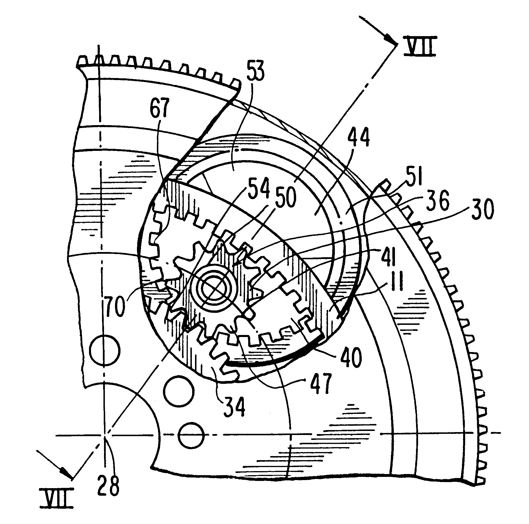
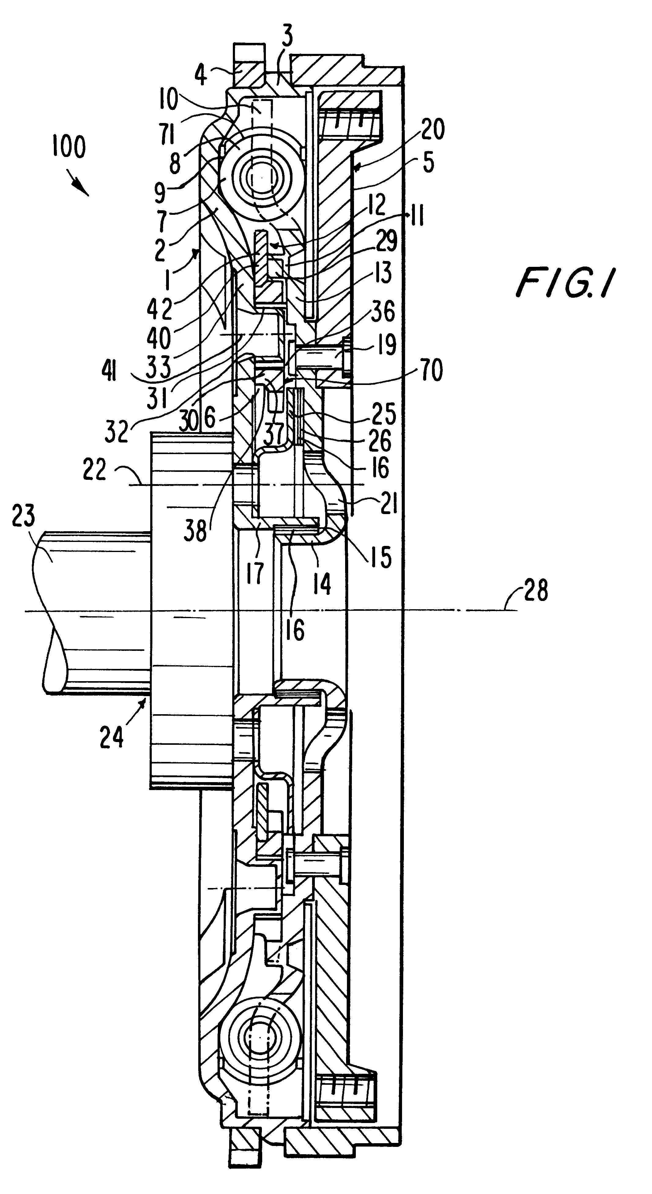
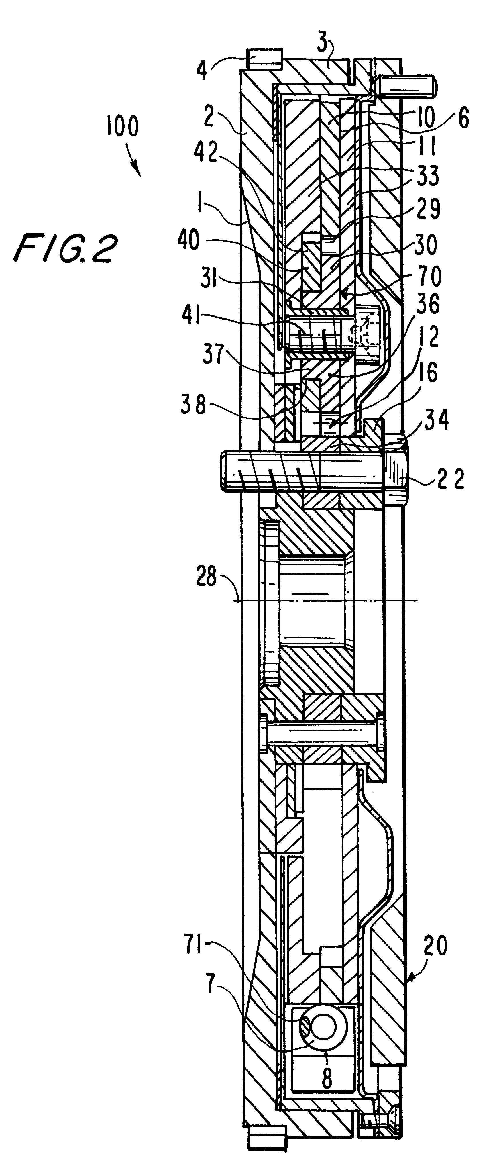
A torsional vibration damper 100 according to the invention is shown in FIG. 1 having a drive-side transmission element 1 in the form of a centrifugal mass with a radially outwardly directed primary flange 2. An outermost circumferential area of the primary flange 2 has an axial edge 3, onto which a toothed gear rim 4 is placed for engaging a starter pinion (not shown). A sealing plate 5 is attached to the axial edge 3 which extends radially inward. The sealing plate 5, together with the axial edge 3 and the primary flange 2, borders a grease chamber 6.
Elastic elements 7 arranged in the grease chamber 6 run circumferentially in the radially outer area and act as a coupling device 71 for a damping device 8. The elastic elements 7 are compressed between control elements 9 on the primary flange 2 and fingers 10 which project radially outward from a hub disk 13 that is connected to the output-side transmission element 20. The hub disk 13 is connected securely with an internal gear 11 of...
PUM
 Abstract
Description
Claims
Application Information