Magneto-resistive asymmetry correction circuit

Inactive Publication Date: 2002-06-04
WESTERN DIGITAL TECH INC
View PDF10 Cites 94 Cited by
  • Summary
  • Abstract
  • Description
  • Claims
  • Application Information

AI Technical Summary

Benefits of technology

to provide a magneto-resistive asymmetry correction circuit that solves the above mentioned prob

Problems solved by technology

This method of correction of asymmetry is complicated.
Many of the prior asymmetry correction schemes depend on changing head bias current or using mat

Method used


Image

  • Magneto-resistive asymmetry correction circuit
  • Magneto-resistive asymmetry correction circuit
  • Magneto-resistive asymmetry correction circuit

Examples


Embodiment Construction

)

The invention will now be described in more detail by way of example with reference to the embodiment(s) shown in the accompanying figures. It should be kept in mind that the following described embodiment(s) is / are only presented by way of example and should not be construed as limiting the inventive concept to any particular physical configuration.

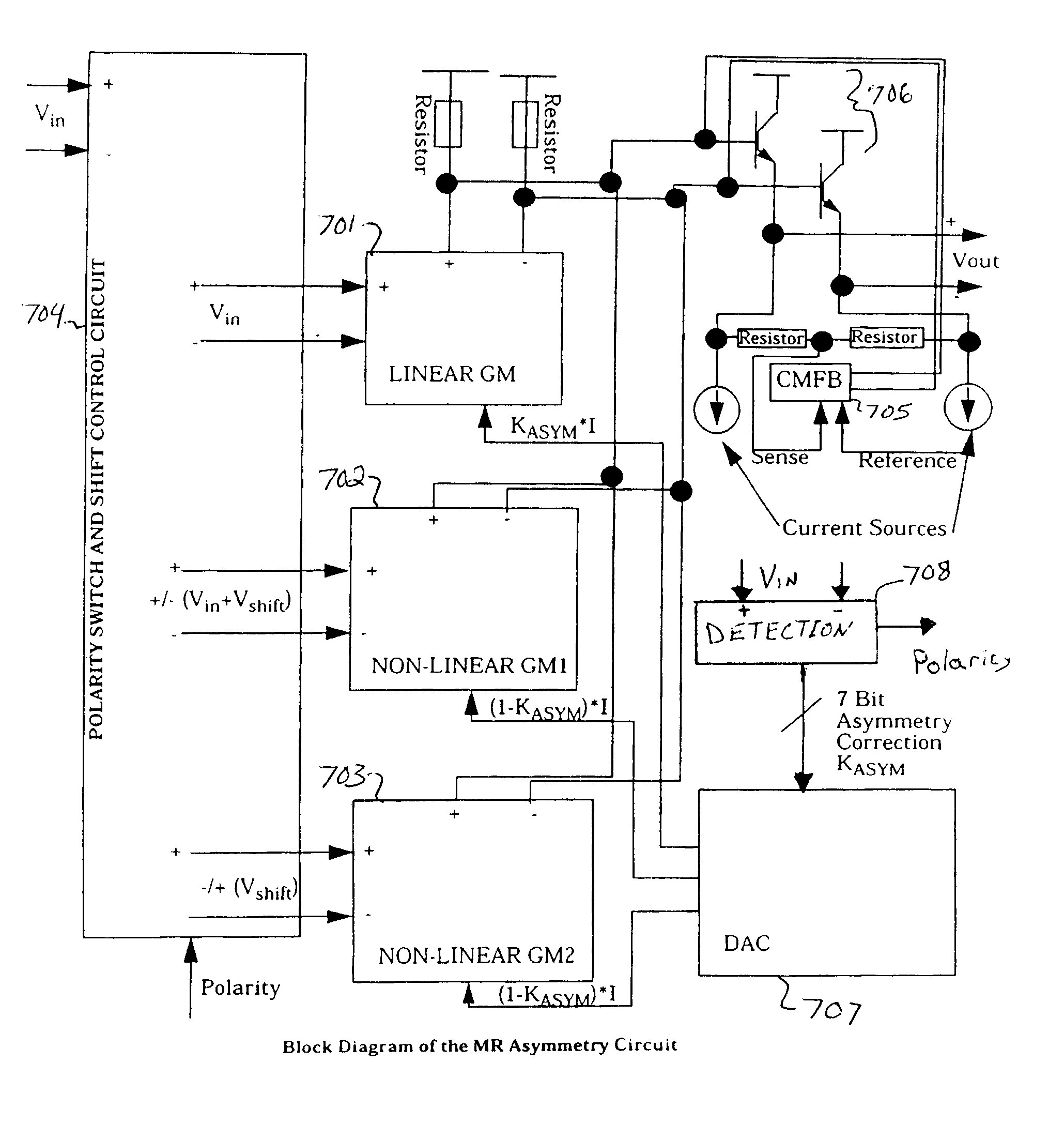
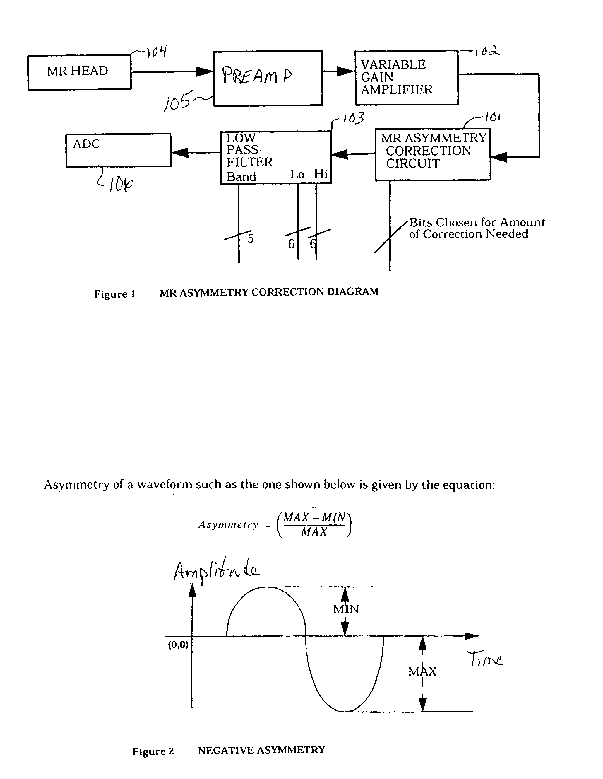
As already explained, the magneto-resistive (MR) heads currently used in disk-drives sometimes produce asymmetric pulses due to various reasons which include temperature and bias point variation. The purpose of the invention implemented in the exemplary circuit described below, is to take such an asymmetric waveform and shape it such that the positive and negative pulses are equal (i.e. symmetrical). That is, correcting asymmetry is advantageously achieved, not just detection or measurement of an amount of asymmetry.

FIG. 1 illustrates a block diagram of a magneto-resistive head asymmetry correction arrangement according to an exemplary ...


PUM


Abstract

A circuit arrangement for correcting magneto-resistive head asymmetry includes a shift circuit which receives a read signal from a magneto-resistive head, and a polarity signal indicative of the polarity of any asymmetry of the read signal. Depending on the polarity of the asymmetry, the shift circuit either adds or subtracts a shift voltage to the read signal to produce a shifted read signal. The shift circuit outputs the read signal, the shifted read signal, and the shift voltage. First, second and third gain circuits are provided, which receive the read signal, the shifted read signal, and the shift voltage, respectively, and which each receive a respective control signal. The first, second and third gain circuits provide respective outputs amplified proportionally based on the respective control signals. Control circuitry provides the polarity signal to the shift circuit and the respective control signals to the first, second and third gain circuits, based on an amount of correction required. A common-mode-feedback circuit adjusts for changes in the common-mode caused by the waveform shaping.

Description

1. Field of the InventionThe invention relates to the field of magneto-resistive heads, and in particular, to circuitry for correcting asymmetry in the output (read signal) from these heads.2. Background InformationThe magneto-resistive heads currently used in disk-drives sometimes produce asymmetric pulses due to various reasons which include temperature and bias point variation.Asymmetry of a waveform such as the one shown in FIG. 2 is given by the equation:Asymmetry=(MAX-MIN) / MAXSo for example if MIN is 30 mV and MAX is 60 mV (absolute value), the asymmetry would be 50%. This would be defined as negative asymmetry (shown in FIG. 2).The problem of asymmetry has been solved before using circuit techniques. The purpose of a correction circuit is to take such an asymmetric waveform and shape it such that the positive and negative pulses are equal (i.e. symmetrical).U.S. Pat. No. 6,072,647, shows a method of correcting MR Head Asymmetry by changing the bias current in the head. This i...

Claims


Application Information

Patent Timeline
IPC IPC(8): G11B5/02G11B5/00G11B5/09G11B5/39
CPCG11B5/02G11B2005/0018G11B5/39
Inventor BHAUMIK, JAYDIPKERTIS, ROBERT ANDREWKLAASSEN, KLAAS BERENDRICHETTA, RAYMOND ALANVAN PEPPEN, JACOBUS CORNELIS LEONARDUS
Owner WESTERN DIGITAL TECH INC
Why Eureka
Try Eureka