Electronic system with self-test function and simulation circuit for electronic system

a technology of electronic system and simulation circuit, which is applied in the direction of instruments, measurement devices, computing, etc., can solve the problems of considerable cost and computer cost of logical simulation

Inactive Publication Date: 2002-06-04
MITSUBISHI ELECTRIC CORP
View PDF2 Cites 34 Cited by
  • Summary
  • Abstract
  • Description
  • Claims
  • Application Information

AI Technical Summary

Problems solved by technology

Accordingly, in the state of the art, the logical sim...

Method used


Image

  • Electronic system with self-test function and simulation circuit for electronic system
  • Electronic system with self-test function and simulation circuit for electronic system
  • Electronic system with self-test function and simulation circuit for electronic system

Examples


embodiment 1

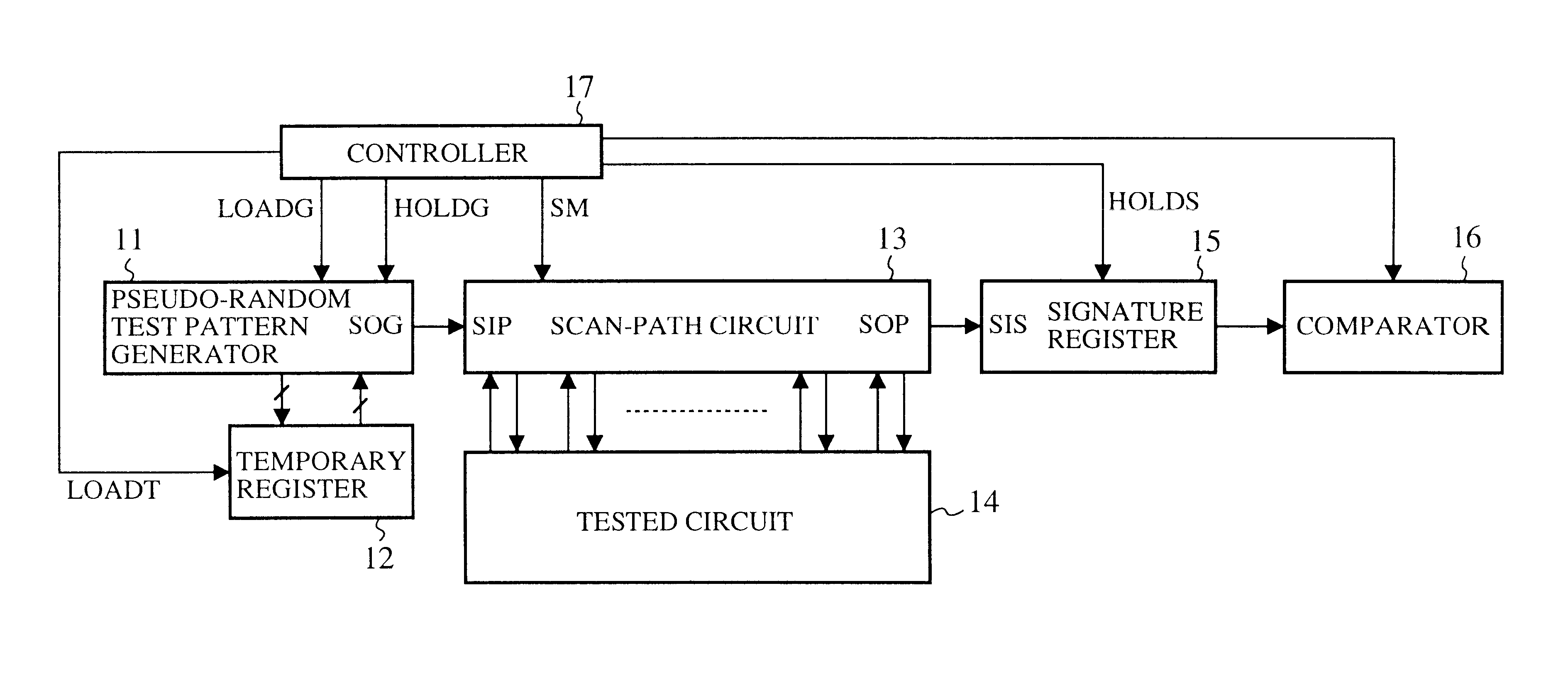
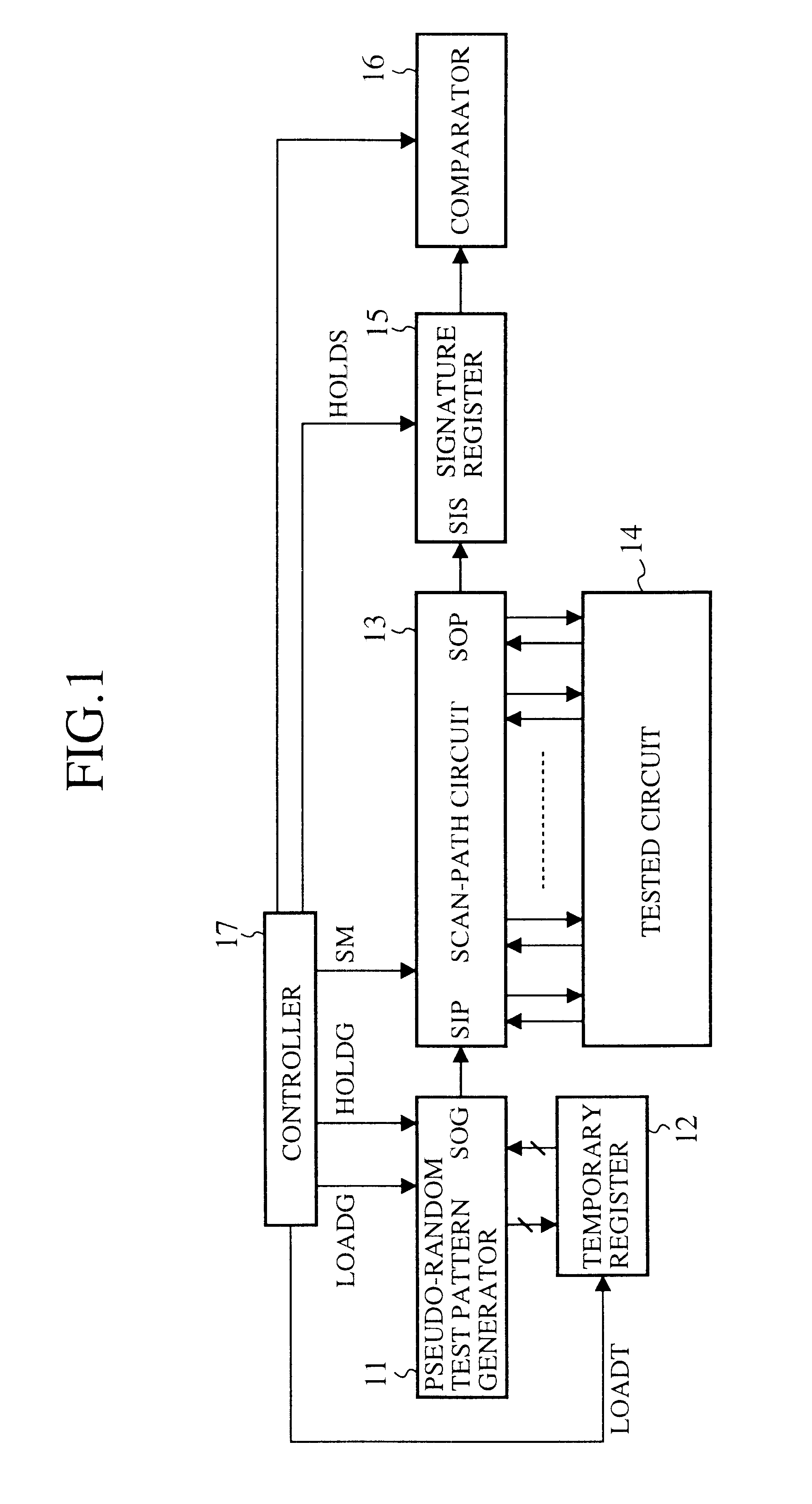
FIG. 1 is a block diagram showing an electronic system with a self-test function in accordance with the present invention. In FIG. 1, the reference numeral 11 designates a pseudo-random test pattern generator for serially generating data constituting a pseudo-random test pattern; 12 designates a temporary register for storing, when the pseudo-random test pattern generator 11 starts the serial output of the data constituting the pseudo-random test pattern, a pseudo-random test pattern which is shifted by one bit; 13 designates a scan-path circuit that acquires a pseudo-random test pattern by serially loading the data serially output from the pseudo-random test pattern generator 11, and supplies a tested circuit 14 with the pseudo-random test pattern in parallel, and that receives an operation result of the tested circuit 14 in parallel, and serially outputs data constituting the operation result. The scan-path circuit 13 is a circuit similar to the conventional scan-path circuit 2 as...

embodiment 2

Although the number of the output terminals of the tested circuit 14 is identical to the number of the stages of the scan flip-flops SFF0-SFF8 constituting the scan-path circuit 13 in the foregoing embodiment 1, this is not essential. For example, when the number of the output terminals of the tested circuit 14 is less than the number of the stages of the flip-flops constituting the scan-path circuit 13 as shown in FIG. 9, the scan-path circuit 13 can be configured as follows.

More specifically, flip-flops RFF6-RFF8 in the scan-path circuit 13, which are not connected to the output terminals of the tested circuit 14, can be configured such that they load "0" (fixed value) when the scan-path circuit 13 loads the operation result of the tested circuit 14 in parallel (when the signal SM=0, AND circuits constituting the flip-flops RFF6-RFF8 always output "0").

Thus, the simulation system corresponding to the electronic system as shown in FIG. 9 can be configured as shown in FIG. 10. Since...

embodiment 3

Although the flip-flops RFF6-RFF8 which are not connected to the output terminals of the tested circuit 14 are provided in initial stages of the scan-path circuit 13 in the foregoing embodiment 2, flip-flops RFF0-RFF2 which are not connected to the output terminals of the tested circuit 14 can be provided in final stages of the scan-path circuit 13 as shown in FIG. 11.

The flip-flops RFF0-RFF2 in the scan-path circuit 13, which are not connected to the output terminals of the tested circuit 14, can be configured just as the flip-flops RFF6-Rff8 in the foregoing embodiment 2. That is, they load "0" (fixed value) when the scan-path circuit 13 loads the operation result of the tested circuit 14 in parallel (when the signal SM=0, AND circuits constituting the flip-flops RFF0-RFF2 always output "0").

Thus, the simulation system corresponding to the electronic system as shown in FIG. 11 can be configured as shown in FIG. 12. Since the simulation system of FIG. 12 operates as that of FIG. 8,...


PUM


Abstract

An electronic system with a self-test function has a pseudo-random test pattern generator that serially generates data constituting a pseudo-random test pattern, and stores a 1-bit shifted pseudo-random test pattern obtained by shifting the pseudo-random test pattern by one bit. When a scan-path circuit supplies the pseudo-random test pattern to a tested circuit which carries out an operation based on the pseudo-random test pattern, and then loads an operation result of the tested circuit, the 1-bit shifted pseudo-random test pattern is supplied to the tested circuit as the next pseudo-random test pattern. This makes it possible to solve a problem of a conventional electronic system in that it takes a long time to evaluate the operation results of the tested circuit because it takes at least (1+n)xm clock cycles, where m is the number of pseudo-random test patterns supplied to the tested circuit and n is the number of stages of the scan-path circuit.

Description

1. Field of the InventionThe present invention relates to an electronic system with a self-test function capable of evaluating operation results of a tested circuit, and a simulation system of the electronic system capable of simulating the operation of the electronic system.2. Description of Related ArtFIG. 23 is a block diagram showing a configuration of a conventional electronic system with a self-test function. In FIG. 23, the reference numeral 1 designates a pseudo-random test pattern generator for serially outputting data constituting a pseudo-random test pattern; 2 designates a scan-path circuit that acquires a pseudo-random test pattern by loading the data serially output from the pseudo-random test pattern generator 1, and supplies a logic circuit to be tested (simply called "tested circuit" from now on) 3 with the pseudo-random test pattern in parallel, and that loads an operation result of the tested circuit 3 in parallel, and serially outputs data constituting the operat...

Claims


Application Information

Patent Timeline
IPC IPC(8): G01R31/3181G01R31/28G01R31/3185
CPCG01R31/31813G01R31/318547G01R31/318385
Inventor MAENO, HIDESHI
Owner MITSUBISHI ELECTRIC CORP
Why Eureka
Try Eureka