

Heat exchanger only using plural plates
a technology of heat exchanger and plate, which is applied in the direction of indirect heat exchanger, laminated elements, light and heating apparatus, etc., can solve the problems of deteriorating the assembling performance of the refrigerant evaporator, affecting the efficiency of the heat exchanger, and causing overpressure loss
- Summary
- Abstract
- Description
- Claims
- Application Information
AI Technical Summary
Benefits of technology
Problems solved by technology
Method used
Image

Examples
first embodiment
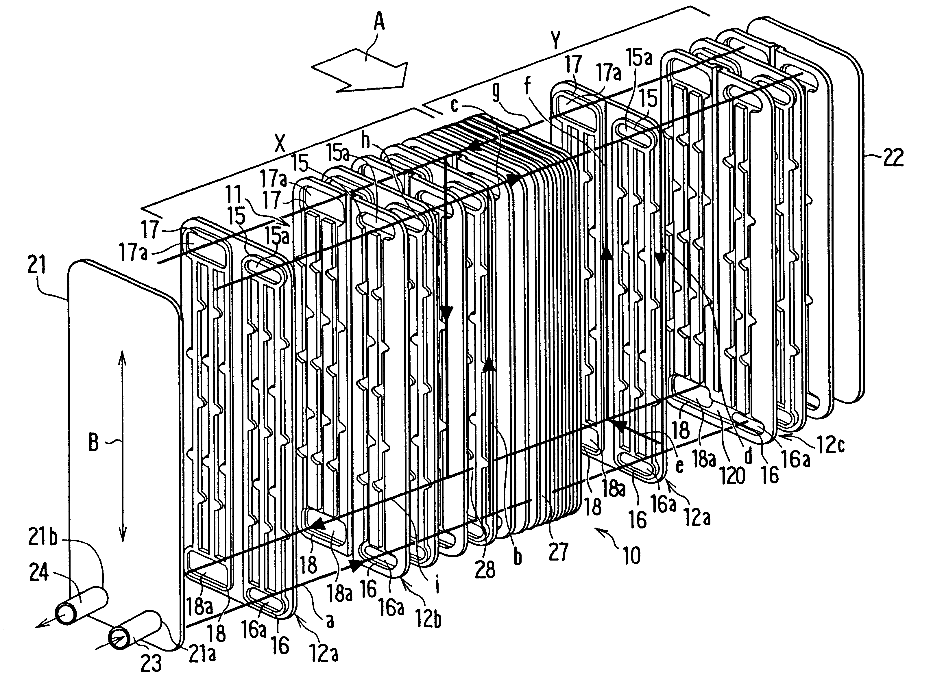
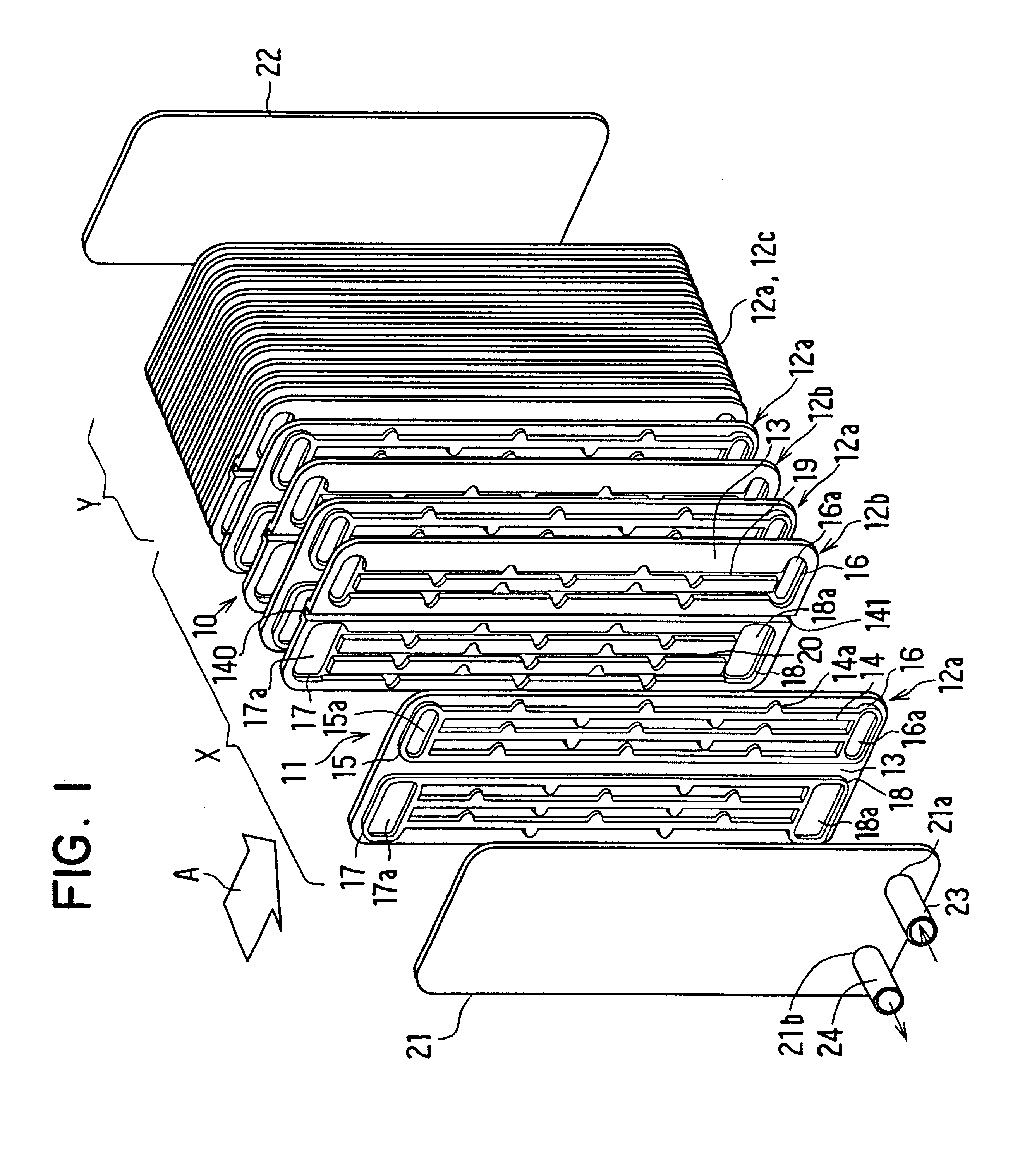
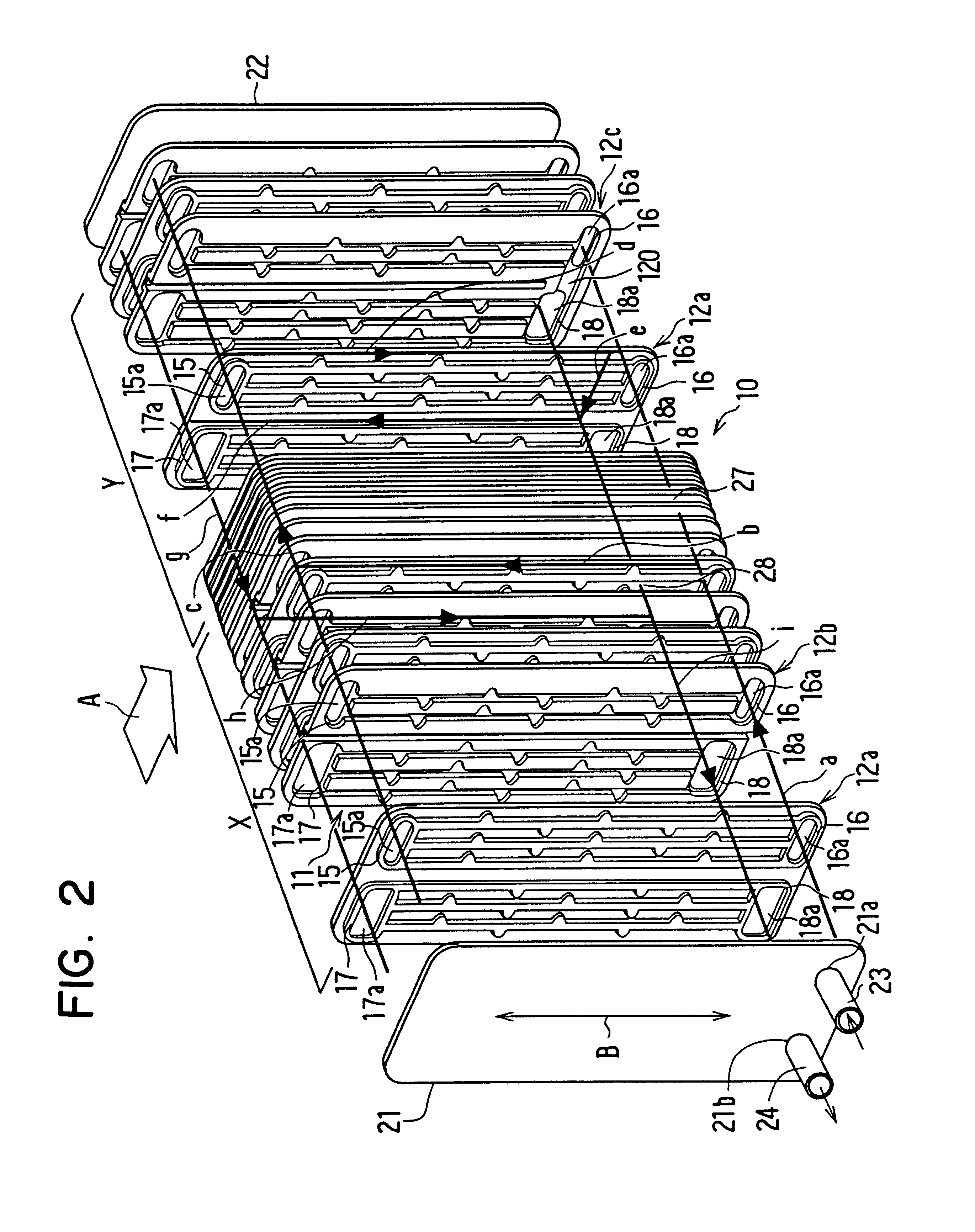
A first preferred embodiment of the present invention will be now described with reference to FIGS. 1-7. In the first embodiment, the present invention is typically applied to a refrigerant evaporator for a vehicle air conditioner. However, the present invention can be applied to an any heat exchanger for performing a heat-exchange. As shown in FIGS. 1, 2, the evaporator 10 is disposed so that an air-flowing direction A is approximately perpendicular to a refrigerant-flow direction B shown in FIG. 2. The evaporator 10 includes a core portion 11 for performing a heat-exchange between air (i.e., outside fluid) and refrigerant (i.e., inside fluid), which is formed by laminating plural heat-exchanging plates 12a, 12b, 12c in a laminating direction.
That is, in the first embodiment, the core portion 11 is constructed by a heat-exchanging area X (i.e., left area X) and a heat-exchanging area Y (i.e., right area Y). The left area X is formed by combining plural first heat-exchanging plates ...
second embodiment
In the second embodiment, the projection ribs 14 are arranged in two lines to be inclined in the same inclination direction. That is, the projection ribs 14 are arranged in an upstream air line and a downstream air line in the heat-exchanging plate 12.
In the second embodiment, the components similar to those in the first embodiment are indicated with the same reference number, and the explanation thereof is omitted. Even in the second embodiment of the present invention, the protrusion pitch P1 shown in FIG. 10 and the passage pitch P2 shown in FIG. 12 has the relationship relative to the heat-exchanging performance, similar to the first embodiment. Therefore, the dimension ranges of the protrusion pitch P1 and the passage pitch P2 can be applied to the evaporator 10 of the second embodiment.
A third preferred embodiment of the present invention will be now described with reference to FIGS. 15 and 16. In the above-described second embodiment, the projection ribs 14 arranged at the up...
fourth embodiment
A fourth preferred embodiment of the present invention will be now described with reference to FIGS. 17, 18. In the fourth embodiment, each of the projection ribs 14 is arranged in a direction perpendicular to the air-flowing direction A. That is, the projection ribs 14 are arranged in parallel with the longitudinal direction of the heat-exchanging plates 12.
According to the fourth embodiment of the present invention, the projection ribs 14 are arranged staggeringly to be parallel to the longitudinal direction of the heat-exchanging plates 12. As shown in FIG. 18, when a pair of the heat-exchanging plates 12 are connected, the projection ribs 14 of the pair of the heat-exchanging plates 12 overlap and communicate with each other at the end portions thereof, so that the refrigerant passages 19, 20 are formed. Thus, according to the fourth embodiment, refrigerant flows through the entire refrigerant passages 19, 20 in parallel with the longitudinal direction of the heat-exchanging pla...
PUM
| Property | Measurement | Unit |
|---|---|---|
| Length | aaaaa | aaaaa |
| Length | aaaaa | aaaaa |
| Length | aaaaa | aaaaa |
Abstract
Description
Claims
Application Information