Eureka AIR delivers breakthrough ideas for toughest innovation challenges, trusted by R&D personnel around the world.

Auxiliary battery for portable devices

a portable device and auxiliary battery technology, applied in the direction of secondary cell maintenance/maintenance, primary cell maintenance/service, instruments, etc., can solve the problems of not being used on different types of portable devices, battery size limitation, and difficulty in producing a battery with a sufficient length of operating tim

Inactive Publication Date: 2002-06-11
TOYO SYSTEM CO LTD
View PDF3 Cites 65 Cited by
  • Summary
  • Abstract
  • Description
  • Claims
  • Application Information

AI Technical Summary

Benefits of technology

The auxiliary battery is able to protect the secondary battery by terminating a charge or discharge operation or disconnecting a charge or discharge circuit when abnormal voltage and / or temperature is detected in the secondary battery. Further, auxiliary battery of the present invention produces a plurality of power outputs with different voltages. The auxiliary battery is able to show the remaining level of power in the secondary battery.

Problems solved by technology

Further, because of high demand for such batteries implemented in portable devices to be small and lightweight, batteries suffer from limitation of the size.
Therefore, it is difficult to produce a battery with a sufficient length of operating time that can satisfy consumers.
However, because the high capacity battery noted above is specifically made for particular portable devices, it can not be used on different types of portable devices.
However, there are various performance limitations in such auxiliary batteries such as not being able to use the portable device while charging the battery, or multiple voltage output terminals cannot be used at the same time.
Therefore, the conventional batteries are not convenient enough for present day portable devices.

Method used


Image

  • Auxiliary battery for portable devices
  • Auxiliary battery for portable devices
  • Auxiliary battery for portable devices

Examples


Embodiment Construction

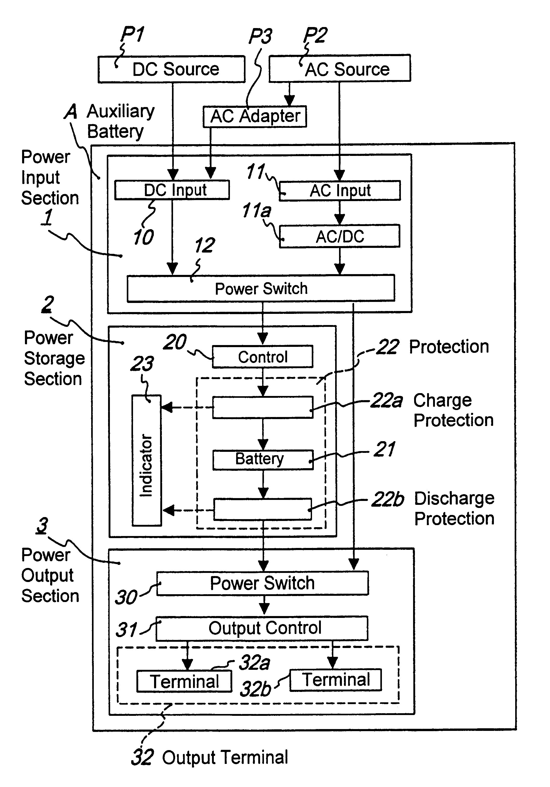
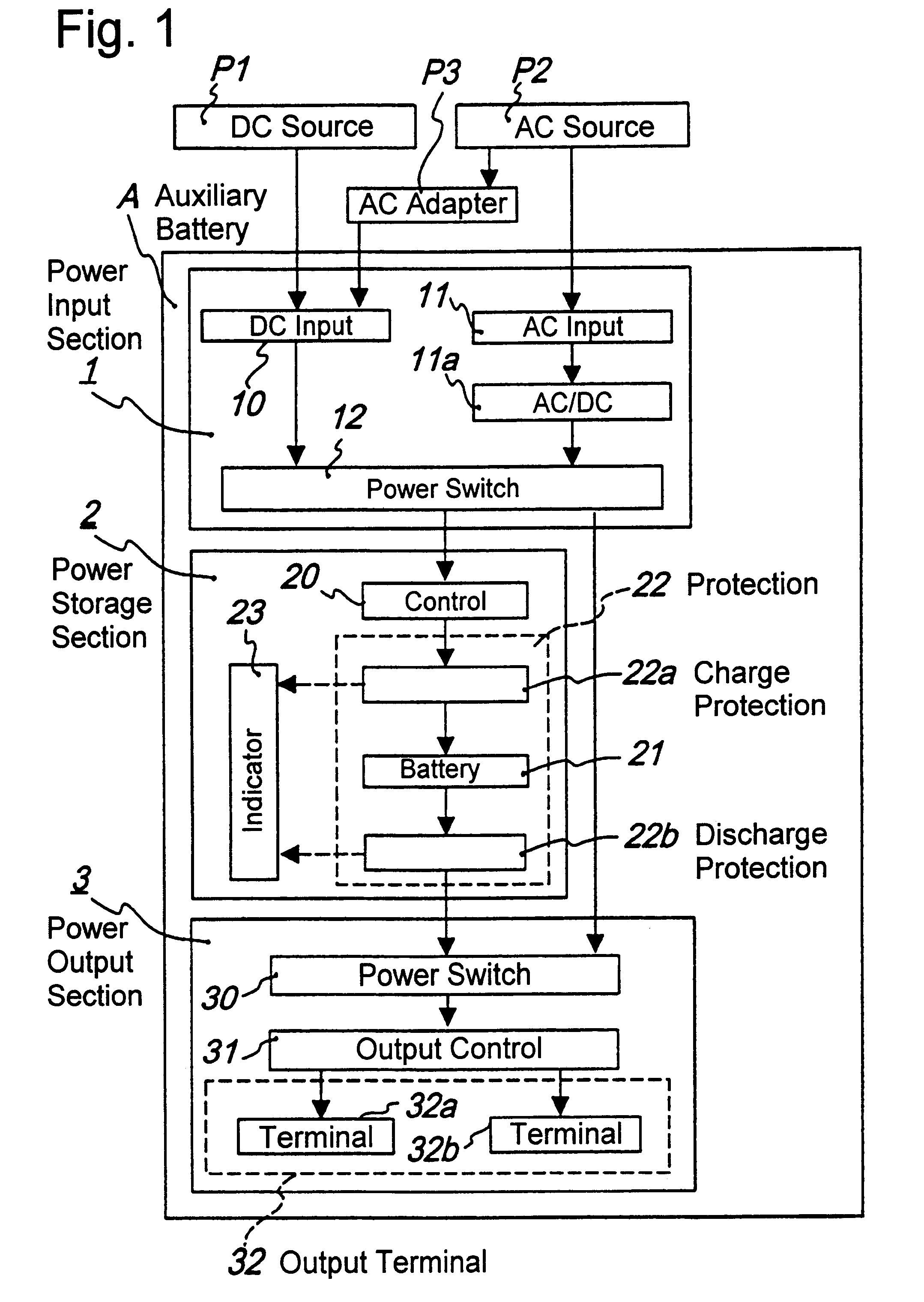
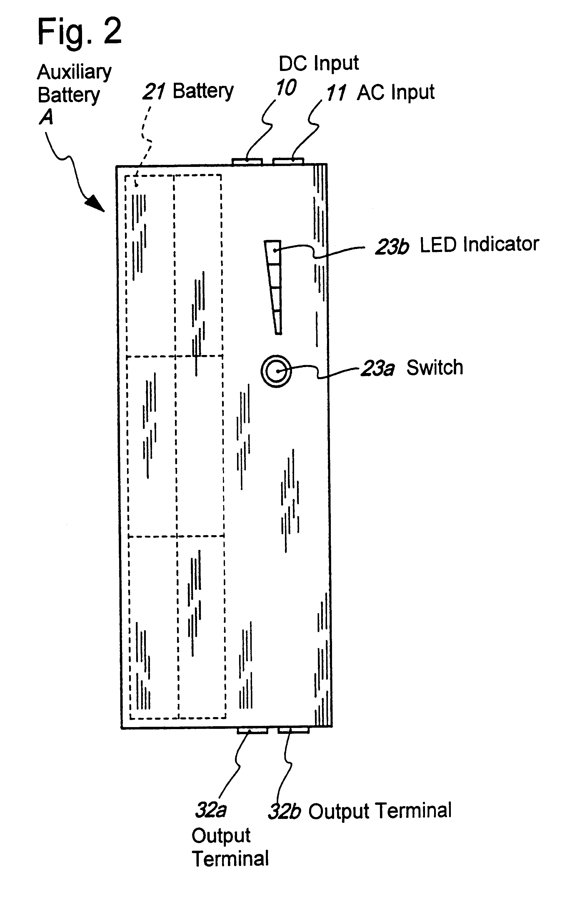
Detailed descriptions of the auxiliary battery of the present invention for portable devices is given below with reference to the drawings. FIG. 1 is a block diagram showing an example of configuration of the auxiliary battery of the present invention. FIG. 2 is a top view of the preferred embodiment of the present invention, and FIG. 3 is a perspective view showing an example of outer appearance of the auxiliary battery of FIG. 2.

In the embodiment of FIG. 1, an auxiliary battery A for portable devices (hereinafter "auxiliary battery"), is comprised of a power input section 1, a power storage section 2, and a power output section 3.

As shown in the block diagram of FIG. 1, the power input section 1 provides the electric power from the external power sources to the power output section 3 and / or power storage section 2. The power input section 1 includes a direct current (DC) input terminal 10 and an alternating current (AC) input terminal 11, and an output power switch circuit 12.

The ...


PUM

PropertyMeasurementUnit
voltageaaaaaaaaaa
voltageaaaaaaaaaa
voltageaaaaaaaaaa

Abstract

An auxiliary battery for portable devices that can be used for a variety of applications with high power capacity. The auxiliary battery includes a power input section for receiving electric power from an external power source, a power storage section having a secondary battery for receiving a charge current from the power input section, a power output section having one or more output terminals for producing electric power at output terminals, and an power switch circuit for selectively inputting electric power to the power output section either from the power input section or from the power storage section.

Description

1. Field of the InventionThis invention relates to an auxiliary battery for portable devices, and more particularly, to an auxiliary battery that can be used for a variety of applications with high electric capacity.2. Description of the Related ArtBecause of the rapid growth of portable devices, a large number of secondary batteries are produced such as lithium ion batteries as internal power sources. Since there are many different types of portable devices, such as notebook PCs (personal computers), cellular phones, audio / video devices and the like, battery voltages in such devices are sometimes different from one another.Further, because of high demand for such batteries implemented in portable devices to be small and lightweight, batteries suffer from limitation of the size. Therefore, it is difficult to produce a battery with a sufficient length of operating time that can satisfy consumers. Therefore, some device makers produce high capacity batteries that are specific to a par...

Claims


Application Information

Patent Timeline
Patent Type & Authority Patents(United States)
IPC IPC(8): H02J7/36H02J1/08H02J7/00H02J7/02H01M10/48H01M10/46H01M10/42H01M2/10H01M10/36H01M10/40H01M10/34H01M6/00H01M6/50H02J7/34G06F1/26H01M10/44H02J9/06
CPCH01M6/5033H02J9/061H01M10/425H01M10/46H01M10/48G06F1/263H01M2/105H01M6/5044H01M10/345H01M10/052Y02E60/10H01M50/213
Inventor SHOJI, HIDEKI
Owner TOYO SYSTEM CO LTD
Why Eureka
Eureka Blog
Learn More