Data compression method for use in wellbore and formation characterization

a data compression and wellbore technology, applied in the field of well logging instruments, can solve the problems of inability to consider the extremely low bandwidth and high noise level of data compression techniques for audio and video data compression and storage, and inability to achieve image transmission.

Inactive Publication Date: 2002-06-11
SCHLUMBERGER TECH CORP
View PDF13 Cites 226 Cited by
  • Summary
  • Abstract
  • Description
  • Claims
  • Application Information

AI Technical Summary

Problems solved by technology

The fluid pressure modulation telemetry systems known in the art, however, are limited to transmitting data at a rate of at most only a few bits per second.
Most prior art data compression techniques for audio and video data compression

Method used


Image

  • Data compression method for use in wellbore and formation characterization
  • Data compression method for use in wellbore and formation characterization
  • Data compression method for use in wellbore and formation characterization

Examples


Embodiment Construction

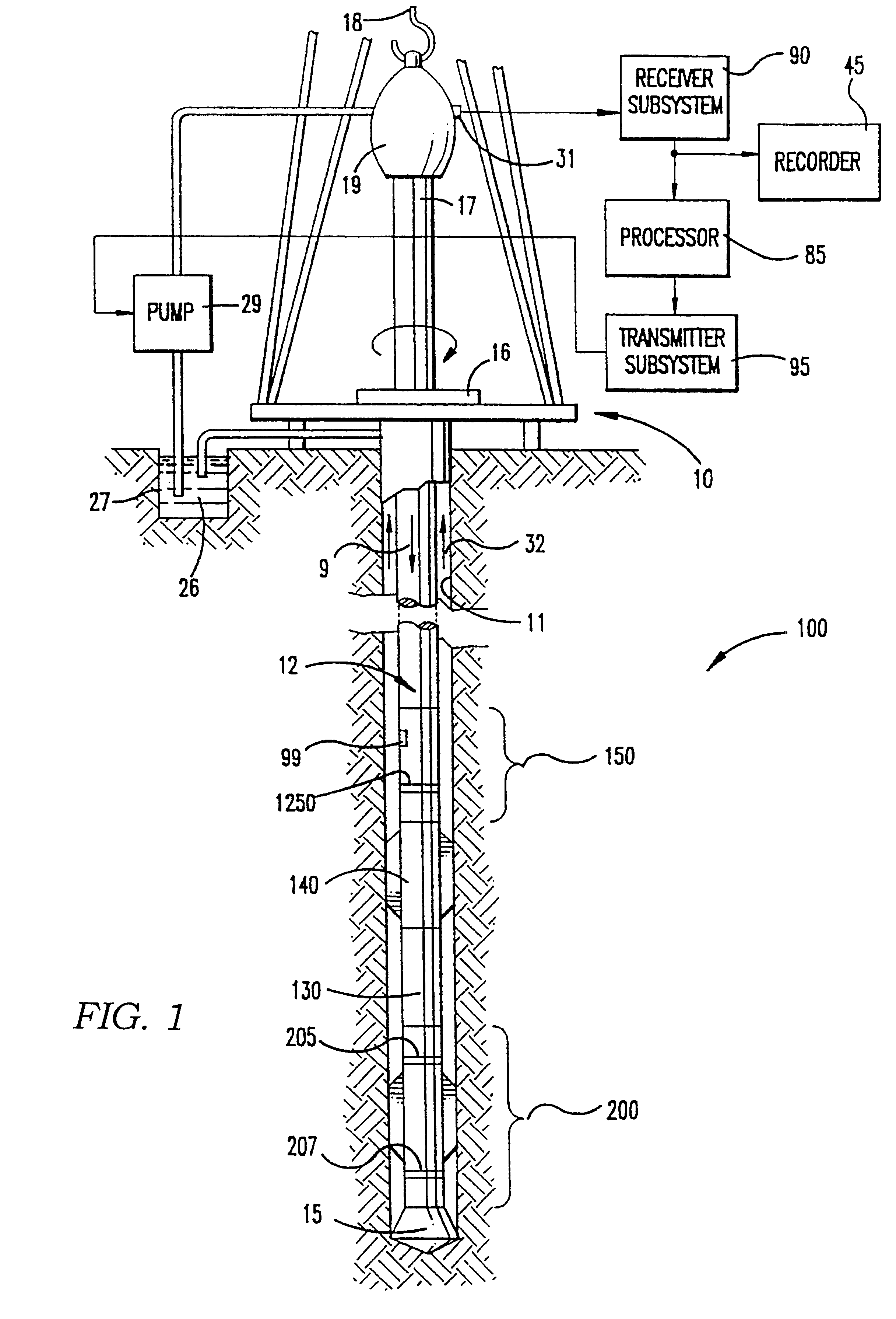
Data Acquisition and Data Compression: Generally speaking, this aspect of the invention relates to data communication between a logging while drilling (LWD) instrument and a recording system located at the earth's surface. Data communication between the LWD instrument and the surface, while the LWD instrument is in a wellbore, is typically performed using various types of pressure modulation on the flow of a drilling fluid through a drilling tool assembly. The drilling tool assembly includes the LWD instrument and an associated fluid pressure modulator. An LWD instrument particularly suited for use with this invention is described in U.S. Pat. No. 5,339,036 issued to Clark et al (Clark '036), incorporated herein by reference. The use of the LWD instrument in conjunction with a measurement while drilling (MWD) instrument and telemetry system is shown generally in FIG. 1. For convenience, the instrument combination of LWD and MWD will be referred to hereinafter as the "LWD instrument"...


PUM


Abstract

A method is disclosed for compressing a frame of data representing parameter values, a time at which each parameter value was recorded, and an orientation of a sensor at the time each parameter value was recorded. Generally the method includes performing a two-dimensional transform on the data in the orientation domain and in a domain related to the recording time. In one embodiment, the method includes calculating a logarithm of each parameter value. In one embodiment, the 2-D transform includes generating a Fourier transform of the logarithm of the parameter values in the azimuthal domain, generating a discrete cosine transform of the transform coefficients in the time domain. This embodiment includes quantizing the coefficients of the Fourier transform and the discrete cosine transform. One embodiment of the method is adapted to transmit resistivity measurements made by an LWD instrument in pressure modulation telemetry so that while-drilling images of a wellbore can be generated. The one embodiment includes encoding the quantized coefficients, error encoding the encoded coefficients, and applying the error encoded coefficients to the pressure modulation telemetry.

Description

The invention is related generally to the field of data communication between wellbore measuring instruments and surface recording systems adapted thereto. More specifically, the invention is related to techniques for compressing data before encoding in a selected telemetry format, and decompressing the data to recover the most significant information contained in the originally measured data.DESCRIPTION OF THE RELATED ARTMany types of well logging instruments have been adapted to make measurements which can be converted into a visual representation or "image" of the wall of a wellbore drilled through earth formations. Typical instruments for developing images include electrical resistivity measuring devices and acoustic reflectance / travel time measuring devices. These instruments measure a property of the earth formations proximate to the wall of the wellbore, or a related property, with respect to azimuthal direction, about a substantial portion of the circumference of the wellbor...

Claims


Application Information

Patent Timeline
IPC IPC(8): H03M7/30
CPCH03M7/30E21B47/04
Inventor LI, QIMINGLOVELL, JOHNFREDETTE, MARK
Owner SCHLUMBERGER TECH CORP
Why Eureka
Try Eureka