Ribbed core dual wall structure

Inactive Publication Date: 2002-06-18
PROTEUS
View PDF20 Cites 64 Cited by
  • Summary
  • Abstract
  • Description
  • Claims
  • Application Information

AI Technical Summary

Benefits of technology

According to a most preferred aspect of this invention, therefore, the ribs are disposed in a helical pattern along the length of the toroidal space between the inner and the outer tubes. In this manner, a buckling of any one rib element, by reason of pressure being applied in the radial direction between flat plates, will not have an unimpeded longitudinal path from one end of the composite tube structure of this invention to the other. Rather, as the ribs pass helically about the hollow inner wall, they form places where they will be disposed directly in the path of the pressure being applied by the opposing flat plates as aforesaid, and will thereby act as a stop to the prog

Problems solved by technology

Solid wood plastic or steel rollers are quite heavy and add to the shipping costs of the material rolled on them.
Further, solid cores of these materials are expensive and, although efforts at recycling have been attempted, they have not met with great success.
The cost of the cores must then be added t

Method used


Image

  • Ribbed core dual wall structure
  • Ribbed core dual wall structure
  • Ribbed core dual wall structure

Examples


Embodiment Construction

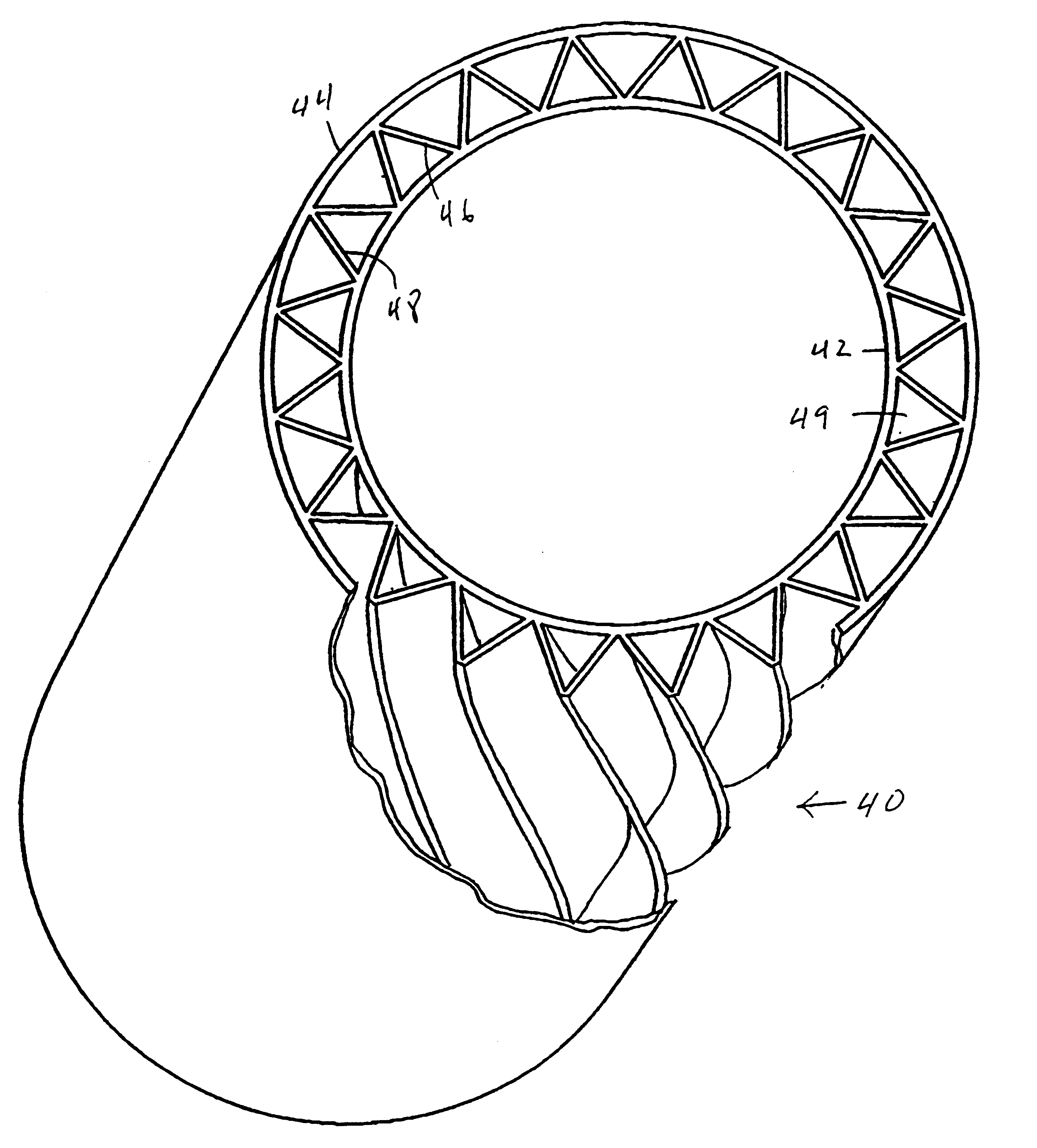
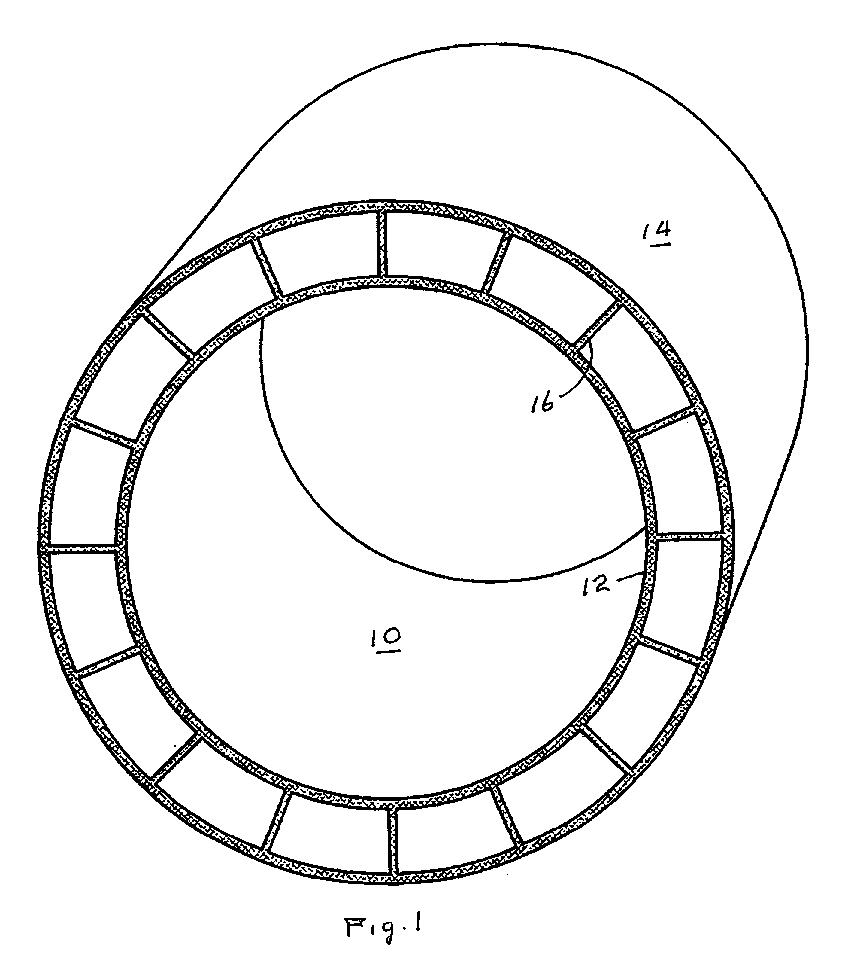
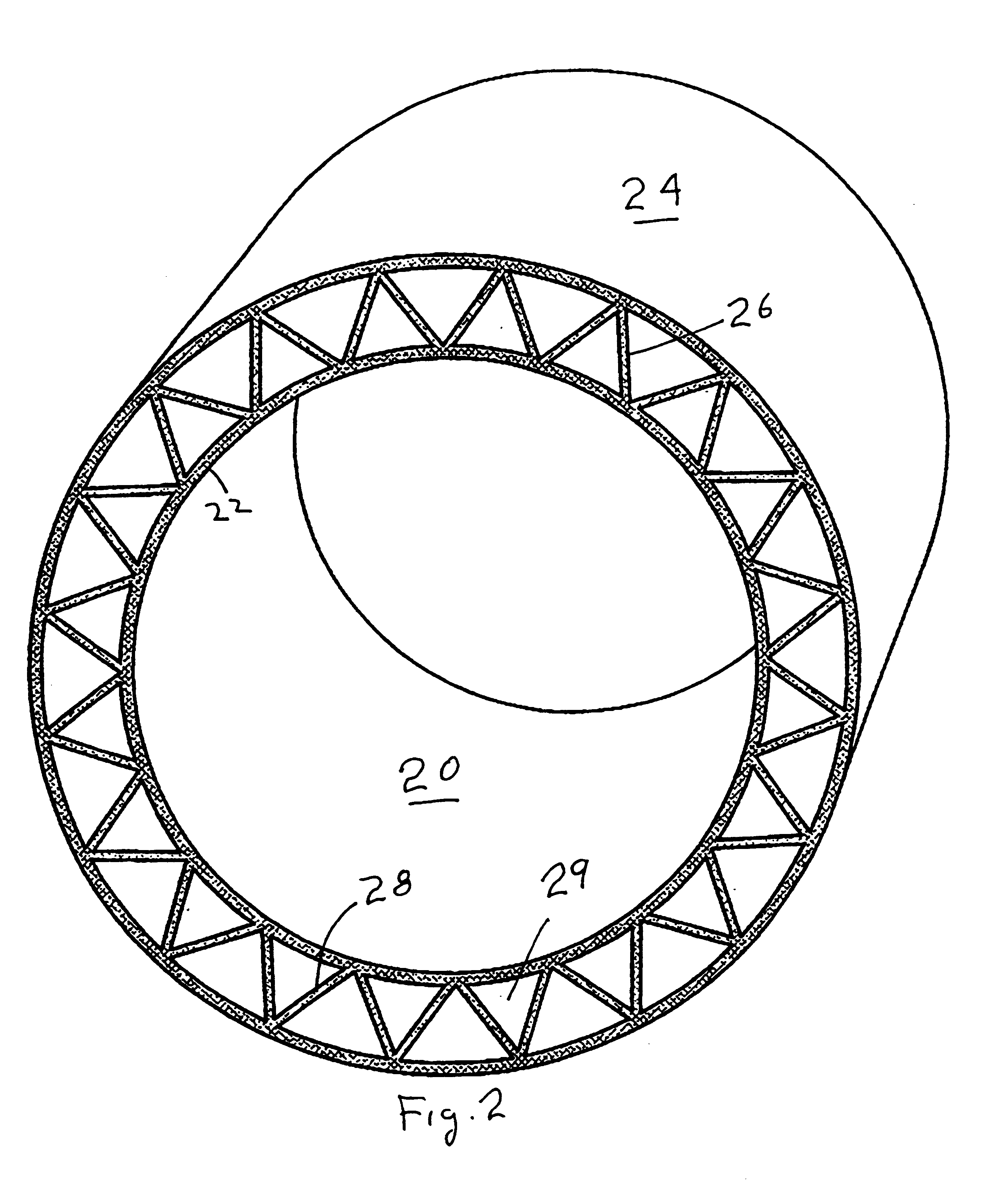
Reference will now be made to the drawing, wherein like parts have been given like reference numbers. Referring to FIG. 1, a composite tube 10 according to this invention is made up of an inner tube 12, an outer tube 14 and a plurality of ribs 16 therebetween. Referring to FIG. 2, a modified composite tube 20 of this invention is made up of an inner tube 22, and outer tube 24, a set of "left handed" "off radial" ribs 26 and an alternating set of right handed" "off-radial" ribs 28. Note that the combination of the inner tube, the outer tube and the two sets of ribs forms generally triangular truss cells 29. Referring to FIG. 4, a further modified composite tube 40 of this invention is made up of an inner tube 42, an outer tube 44, and a series of left and right handed alternating "off-radial ribs" 46 and 48, respectively. Note that the left and right handed ribs contact and are joined to the inner and outer tubes, respectively, out of contact with each other. This is to be compared t...


PUM

PropertyMeasurementUnit
Lengthaaaaaaaaaa
Angleaaaaaaaaaa

Abstract

An elongated composite tube made up of an inner tube 42 and an outer tube 44 (FIG. 3) with a plurality of elongated helical ribs disposed between the inner tube and the outer tube in a supporting relationship to both. A slinky like toy made from the composite tube is also disclosed, as is a method of making both.

Description

GENERAL FIELD OF THE INVENTIONThis invention relates to generally tubular articles such as cores for rolled goods like carpets and plastic film. It more particularly refers to such cores that are light in weight and have unusually high crush resistance. It further relates to decorative toy articles made from such tubular articles.Cores for all kinds of rolled goods, such as plastic film, carpeting, paper products, and the like, are well known. In many instances, these cores are simply hollow cylindrical rolls of cardboard or other materials. In other cases, these cores may be solid plastic, wood or metal rods.In one very old patent, U.S. Pat. No. 3,627,221, there is described a decorative end plug for rolled paper, such as newsprint. The end plug is made up of a centrally located opening for receiving an axially disposed shaft, a generally flat, solid, disc like portion 16 disposed radially about the shaft receiving axial opening 18, and a peripheral rim portion 20 disposed radially...

Claims


Application Information

Patent Timeline
IPC IPC(8): B29C53/00B29C53/14B29C47/20F16L9/18F16L9/19B29C48/11B29C48/13B29C48/32B29C48/355
CPCB29C47/0023B29C47/005B29C47/065B29C47/12B29C53/14F16L9/19B29C47/0028Y10T428/139B29C47/003B29C47/0033B29C47/0038B29C47/0057B29C47/0066B29C47/34B29L2023/00B29L2023/22B29L2024/006B29L2031/60B29L2031/704B29L2031/7732B29C48/09B29C48/11B29C48/12B29C48/13B29C48/001B29C48/0015B29C48/0018B29C48/0022B29C48/21B29C48/33B29C48/355
Inventor HERRINGTON, F. JOHN
Owner PROTEUS
Why Eureka
Try Eureka