Pipe fittings

a technology for fittings and pipes, applied in the direction of hose connections, other domestic objects, mechanical equipment, etc., can solve the problems of pipe fittings, pipeline leakage or catastrophic failure, coupling failure,

Inactive Publication Date: 2002-06-18
FINA RES SA
View PDF15 Cites 132 Cited by
  • Summary
  • Abstract
  • Description
  • Claims
  • Application Information

AI Technical Summary

Problems solved by technology

Such known electrofusion pipe fittings suffer from the technical disadvantage that they are limited to fluid pressures in the pipeline of a maximum of 25 bar.
At higher pressures, the electrofused fitting fails, leading to leakage from or catastrophic failure of the pipeline.
The specifications referred to hereinabove suffer from the problem that they are not particularly directed to the manufacture of electrofusion pipe fittings which can be employed with high fluid pressures in the pipeline, typically greater than about 25 bar.
Such mechanical couplings have the technical problem that they are subject to corrosion of the metal, which over time can lead to failure of the coupling.

Method used


Image

  • Pipe fittings
  • Pipe fittings
  • Pipe fittings

Examples


Embodiment Construction

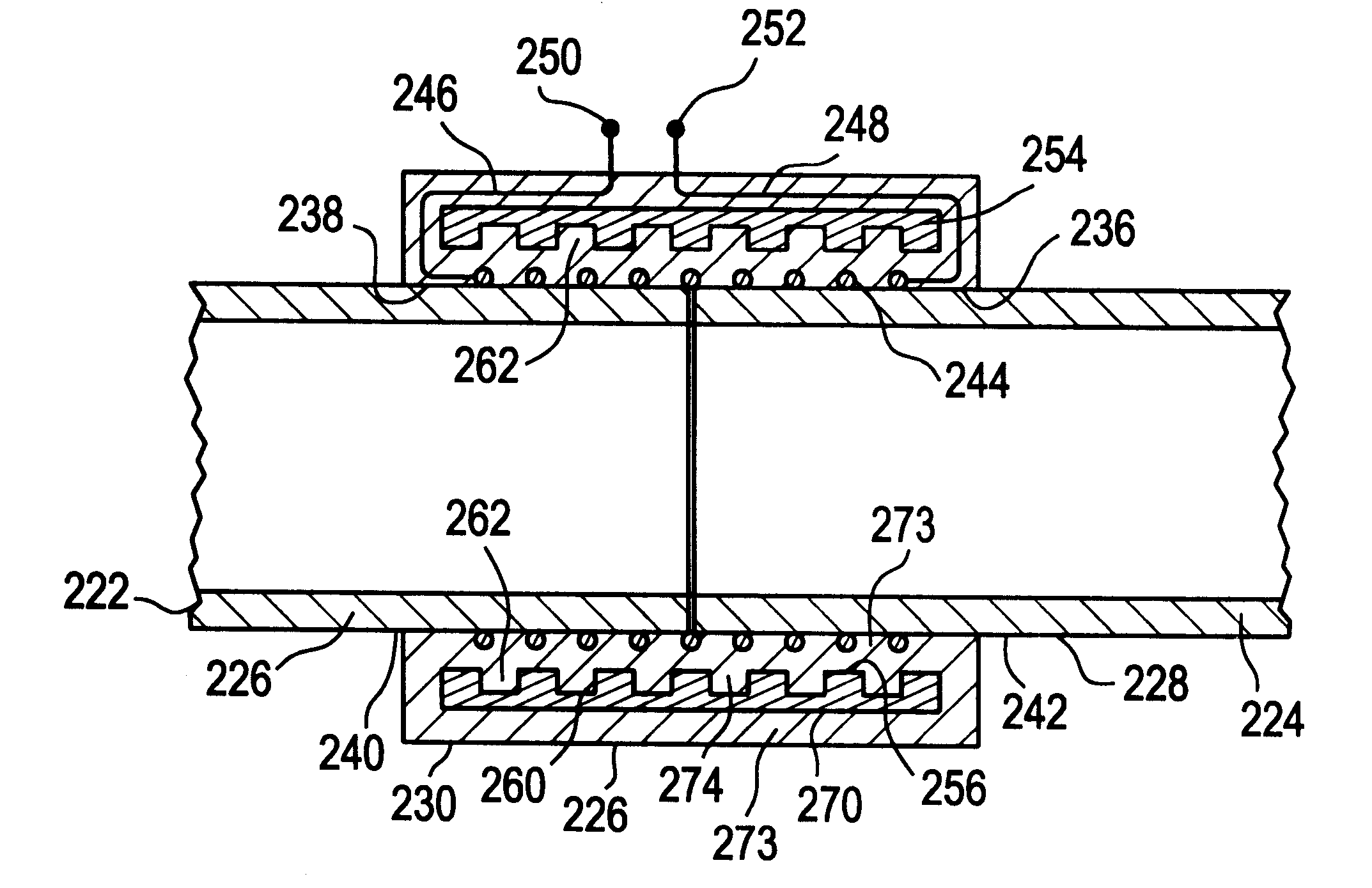
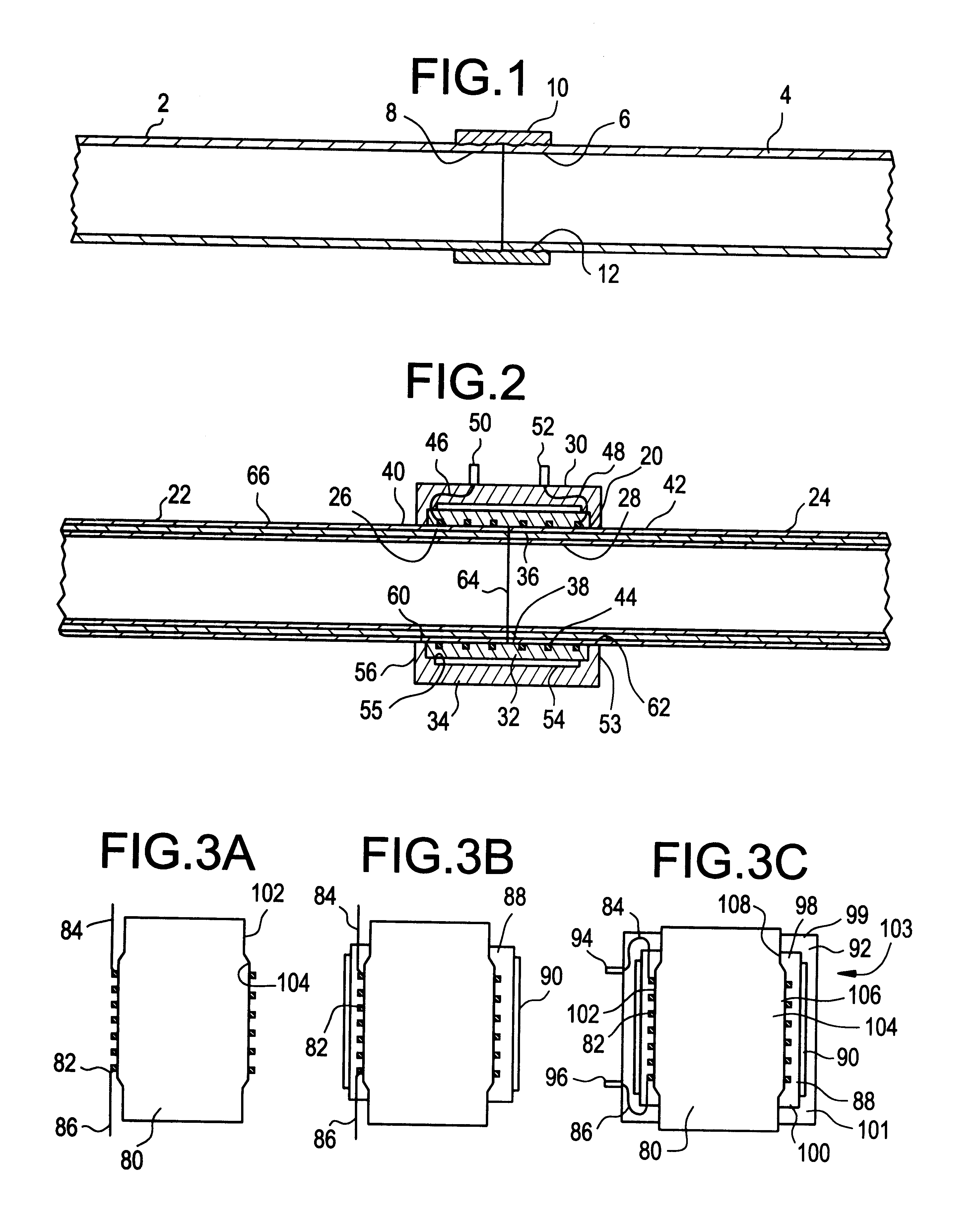
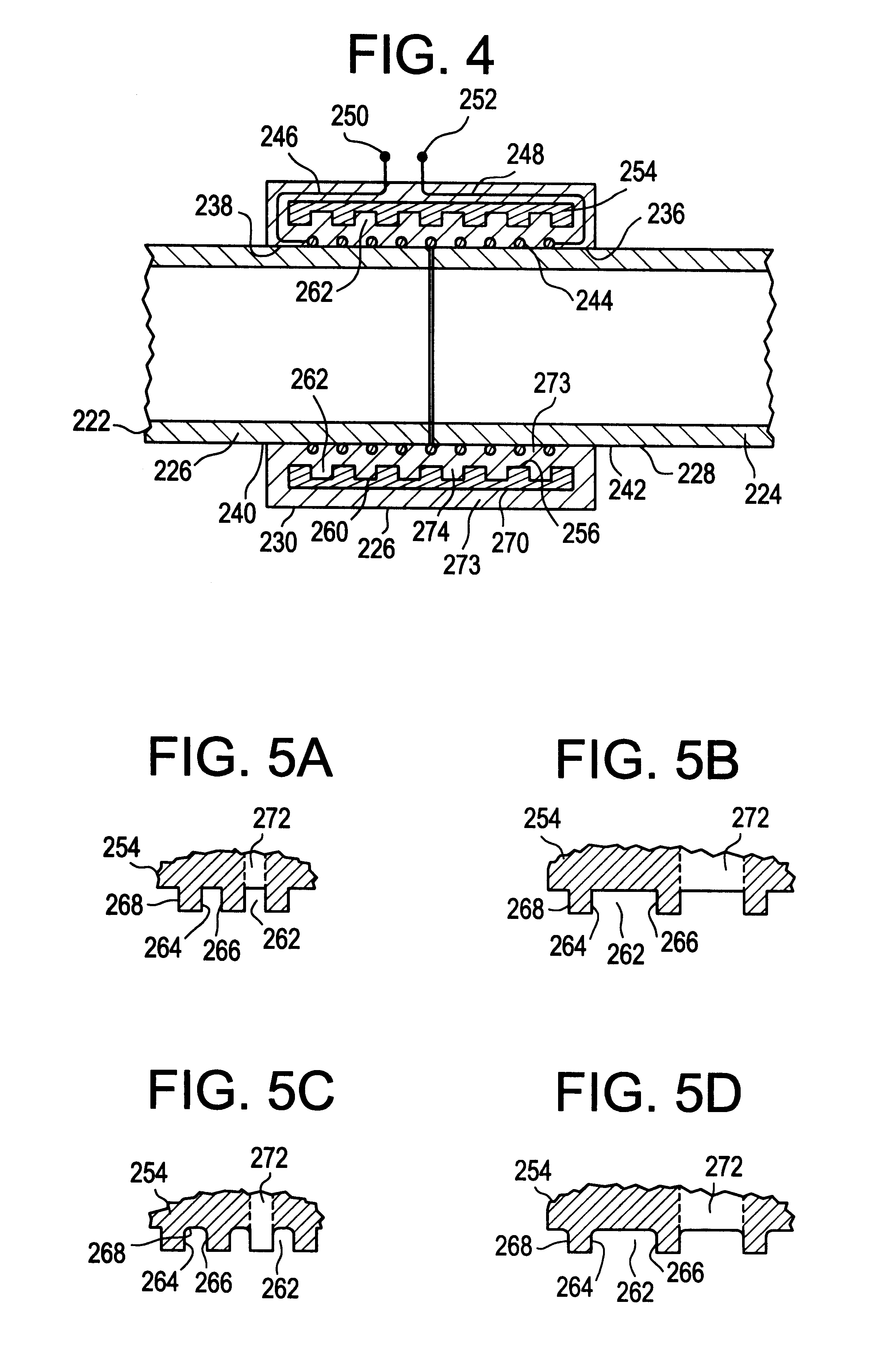
Two pipe fittings having the structure illustrated in FIG. 2 were injection moulded so as to incorporate a metallic annular reinforcing member. The pipe fittings were shaped and dimensioned for coupling together polyethylene pipes which were reinforced to be operable at high internal pressure, the pipes having an external diameter of 40 mm. The pipe fittings were welded by electrofusion welding onto the pipes. The resultant pipeline section was submitted to pressure tests at a temperature of 80 degrees Centigrade. At 80 degrees Centigrade, under a pressure of 60 bars, no failure in the pipeline was observed after a test period of 165 hours. At a temperature of 80 degrees Centigrade, under a pressure of 80 bars, also no failure was observed for a test period of 165 hours. This latter result shows that the electrofusion welding pipe fitting of the invention in combination with a reinforced polyethylene pipe can sustain a pressure 10 times higher than a conventional monolayer polyethyl...


PUM

PropertyMeasurementUnit
tensile strengthaaaaaaaaaa
widthaaaaaaaaaa
depthaaaaaaaaaa

Abstract

A pipe fitting for coupling together opposed ends of two plastics pipes by fusion welding, the pipe fitting comprising an annular body having an inner cylindrical surface of plastics material surrounding a cylindrical cavity for receiving opposed ends of two plastics pipes to be coupled together, an electrically conductive coil provided in said inner cylindrical surface and surrounding the cylindrical cavity, the coil having opposed ends, a pair of terminals each connected to a respective end of the coil and provided on the body for connection to a source of controlled electrical power, and an annular reinforcing member disposed in the body and surrounding the coil, the annular reinforcing member having a grooved surface which interfaces the annular body, the grooved surface defining a plurality of axially facing surfaces.

Description

BACKGROUND TO THE INVENTIONThe present invention relates to pipe fittings, in particular pipe fittings for electrofusion of pipes to form a pipeline. The present invention also relates to a pipeline incorporating a pipe fitting. The present invention yet further relates to a method of producing a pipe fitting.DESCRIPTION OF THE PRIOR ARTPlastics pipes, in particular pipes made of polyethylene, are widely known for use in forming pipelines for conveying fluids such as water or natural gas. Such pipelines are made by joining together a succession of individual pipes using pipe fittings. It is known in the art to use pipe fittings incorporating a heating coil which surrounds the abutting ends of two pipes to be joined together. When an electrical current is passed through the coil, the current causes plastics material in the pipe fitting to melt and to be fused to the plastics material of the two pipes by melt displacement, thereby forming a welded joint which seals the two pipe ends t...

Claims


Application Information

Patent Timeline
Patent Type & Authority Patents(United States)
IPC IPC(8): B29C65/34B29D23/00F16L47/02F16L47/03B29L23/00
CPCB29C65/342B29C66/5221B29C66/52295B29D23/005F16L47/03B29C66/723B29C66/5229B29C66/1222B29C66/1224B29C65/3468B29C65/8246B29C66/721B29C65/3476B29C66/73921B29C66/71B29C66/1122B29C66/1142B29K2023/06
Inventor PFEIFFER, PIETER GEERT
Owner FINA RES SA
Why Eureka
Try Eureka