Process for producing a pneumatic tire

a pneumatic tire and process technology, applied in the field of pneumatic tire production, can solve the problems of the geometry of the carcass, and the displacement of the volume of the superimposed rubber layer,

Inactive Publication Date: 2002-06-18
CONTINENTAL AG
View PDF14 Cites 24 Cited by
  • Summary
  • Abstract
  • Description
  • Claims
  • Application Information

AI Technical Summary

Problems solved by technology

In this situation, there is always the problem that, during the shaping of the cylindrical preform to produce the torus-shaped tire body and during the vulcanization, in which internal pressure is applied to the preform via a bellows and in which the preform is placed under elevated temperature to receive its "residual elevation," it must be considered that the geometry of the carcass can change as a result of each expansion procedure and also that the volumes of the superimposed rubber layers, e.g., the volumes of the tread or of the rubber parts of the sidewall, can be displaced.
However, such compensation or adjustment holds the dangers that, e.g., in the areas particularly subjected to the expansion, exact dosing of the rubber volumes and exact shaping are difficult.
However, the disadvantage of this process is that a further layer, which ensures the adhesion of the individual parts to one another, must be inserted as a rule to bond the carcass and the tread.
As in previous processes that suggest a separate production and vulcanization of a carcass body and its subsequent bonding with the remaining tire components in a separate manufacturing procedure, the problem arises that, due to the second shaping required to combine it with the remaining tire components, increased stresses and compressive strains are introduced into the reinforcing plies and, in particular, also into belt plies already present, i.e., by the residual elevation of the already vulcanized and shape-stable carcass.
An inserted adhesive or bonding layer to reduce the second shaping of the already vulcanized and shape-stable carcass does not fundamentally solve this problem, since this has a disadvantageous effect on the vulcanization process.
In addition, a conflict in aims arises in such a two-part production process.
However, to apply, e.g., the necessary vulcanization pressure among other things, such a small displacement or adjustment path in the radial direction requires a large residual elevation, which, as discussed above, produces the undesirably increased stresses and strains in the carcass components, i.e., in the reinforcing plies and, in particular, also in belt plies already present.
The results of defective tire uniformity are evident in an unsatisfactory running behavior, in increased development of noise, and in a strong load on the bonding areas during operation.
While it is true that the frequently described problem is solved, i.e., that a displacement of the reinforcing plies can also take place during the impressing of the tread profile as a result of the displacements of the volumes in the not yet vulcanized rubber, which has a detrimental effect on the later strength of the tire, the introduction of stresses and strains into the carcass components is not prevented here either, and also this conflict in aims is not resolved.
However, from an economic point of view, this must be correlated with the mold or vulcanization processes that are made more expensive by such a measure, which also include appropriate device adjustments.

Method used


Image

  • Process for producing a pneumatic tire
  • Process for producing a pneumatic tire
  • Process for producing a pneumatic tire

Examples


Embodiment Construction

The particulars shown herein are by way of example and for purposes of illustrative discussion of the embodiments of the present invention only and are presented in the cause of providing what is believed to be the most useful and readily understood description of the principles and conceptual aspects of the present invention. In this regard, no attempt is made to show structural details of the present invention in more detail than is necessary for the fundamental understanding of the present invention, the description taken with the drawings making apparent to those skilled in the art how the several forms of the present invention may be embodied in practice.

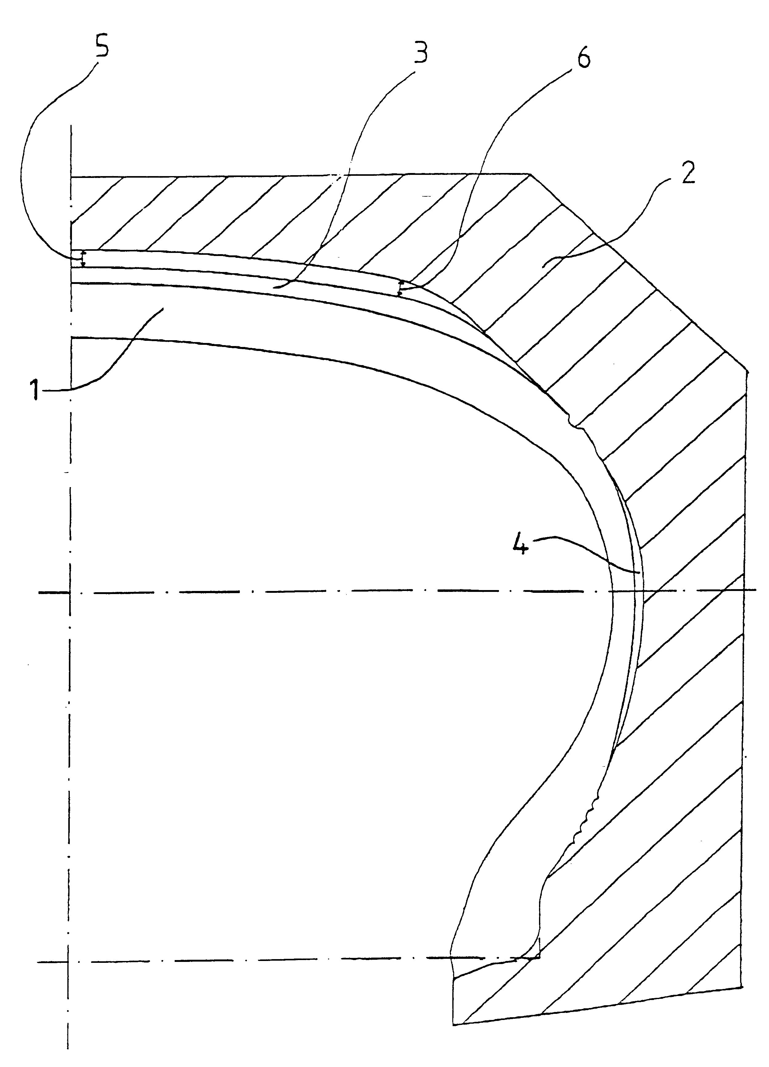
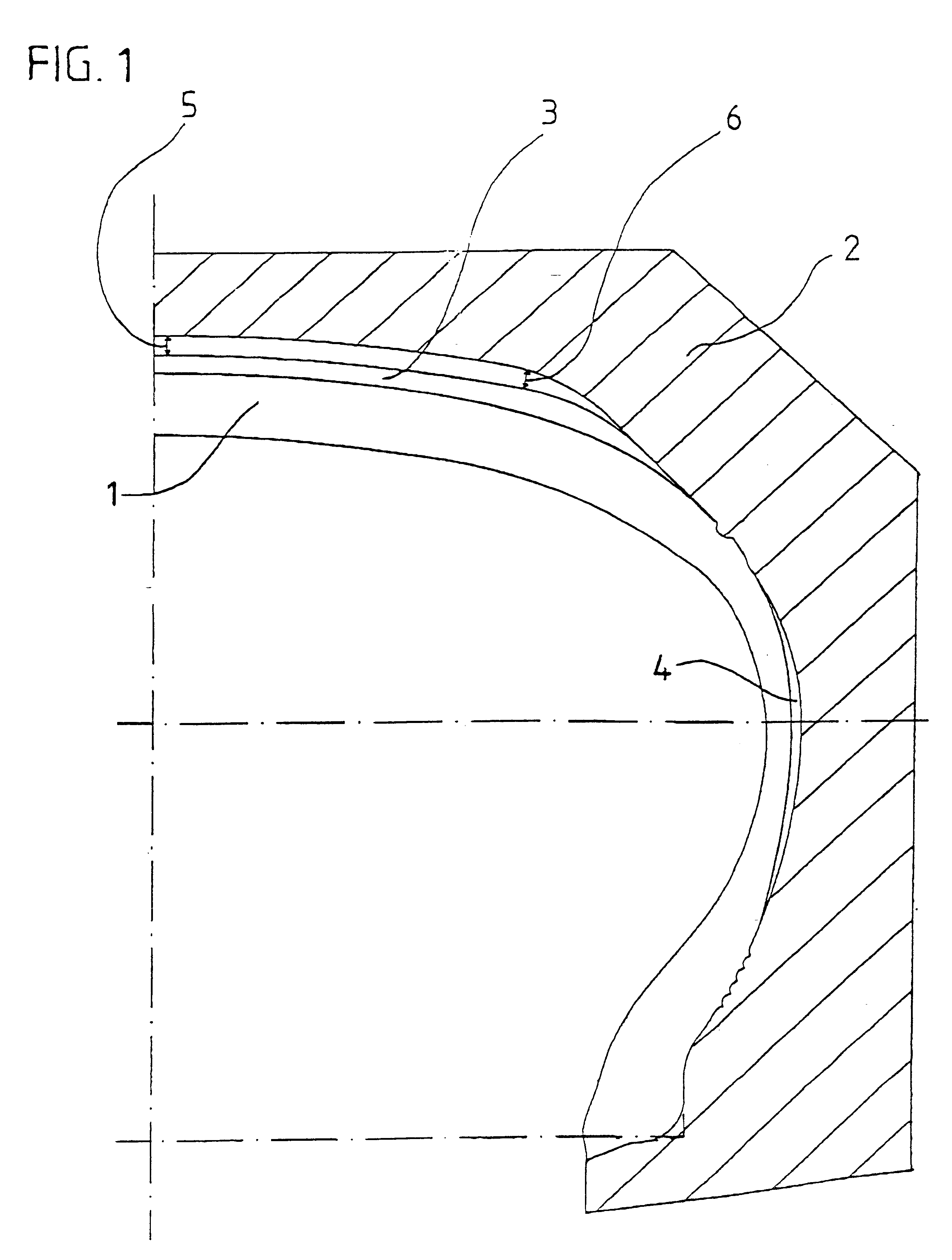
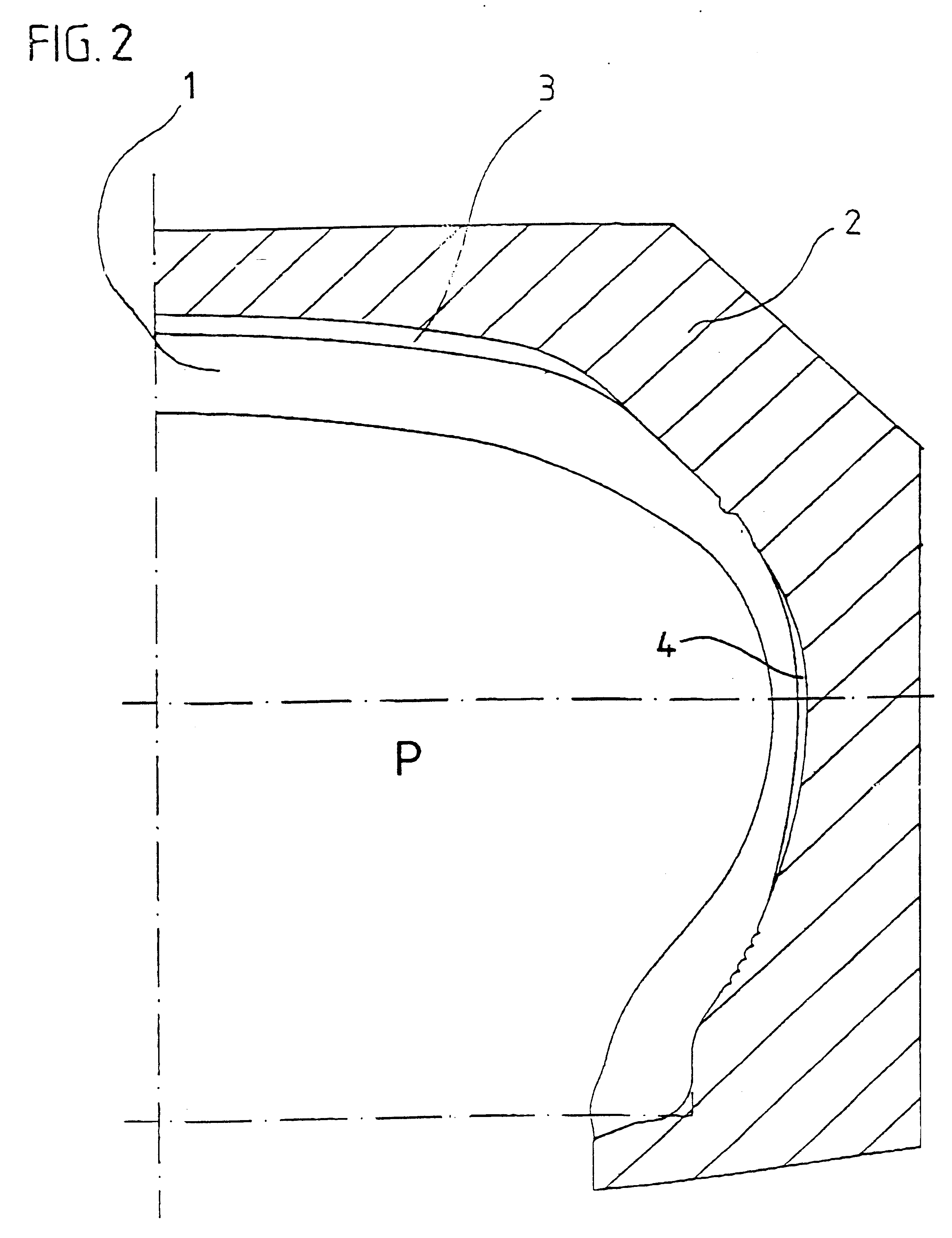
FIG. 1 illustrates in partial cross-sectional view of a partial tire 1, which has already been produced and prevulcanized in a process part A. Partial tire 1 is inserted into a vulcanization mold 2 designed, e.g., as a segmented mold, in which, in process part B, the complete tire is built up after the remaining tire components...


PUM

PropertyMeasurementUnit
angleaaaaaaaaaa
diameteraaaaaaaaaa
diameteraaaaaaaaaa

Abstract

Process for producing a pneumatic tire that includes an inner liner of a layer that is as air-impermeable as possible, at least one carcass ply provided with strength supports, horn profiles, bead cores, sidewalls, a belt assembly, and a tread. The process includes building-up a partial tire in a production part A, where the partial tire includes at least a carcass body that includes the at least one carcass ply provided with the strength supports, bead reinforcements and cores, core fillers and horn profiles, and an undertread, and shaping and at least partially vulcanizing the partial tire under an internal pressure in a vulcanization mold in a first vulcanization procedure. The process also includes determining a cross-sectional contour for a completed tire and an amount of surface and strength supports to be added to the partial tire prior to a production part B, and building-up the partial tire in the production part B by adding remaining tire components to produce a complete tire. Further, the process includes vulcanizing the complete tire in the vulcanization mold, thereby bonding the partial tire to the remaining tire components. While vulcanizing the complete tire, a residual elevation produced by internal pressure is applied, whereby the complete tire is molded to its final contour. The residual elevation in shoulder areas of the completed tire is greater than or equal to the residual elevation in a zenith area.

Description

The present application claims priority under 35 U.S.C. .sctn.119 of German Patent Application No. 199 05 643.9, filed on Feb. 11, 1999, the disclosure of which is expressly incorporated by reference herein in its entirety.1. Field of the InventionThe present invention relates to a process for producing a pneumatic tire, e.g., for motor vehicles, that includes a build-up of the tire with an inner liner of a layer that is as air-impermeable as possible, at least one carcass ply provided with strength supports, horn profiles, bead cores, sidewalls, a belt assembly, an optional one-part or multi-part belt bandage, and a tread. The production process is divided into two separate production parts A and B. In production part A, a partial tire is built up and includes at least the carcass body provided with reinforcing plies, bead reinforcements and cores, core fillers and horn profiles, optionally, parts of the belt plies and / or the belt bandage, and the undertread. The partial tire is sh...

Claims


Application Information

Patent Timeline
Patent Type & Authority Patents(United States)
IPC IPC(8): B29D30/00B29D30/06
CPCB29D30/0601B29D30/0005B29C2791/001
Inventor BAUMGARTEN, RAINERCAMPSHEIDE, OLAFFRIES, VOLKMARJENKE, ROLAND
Owner CONTINENTAL AG
Why Eureka
Try Eureka