
Back-up or intermediate roller for producing a flat rolled product in a rolling mill

Inactive Publication Date: 2002-06-25
SMS DEMAG AG
View PDF2 Cites 5 Cited by
  • Summary
  • Abstract
  • Description
  • Claims
  • Application Information

AI Technical Summary

Benefits of technology

is, by improving a known sleeved roll, to provide an adjusting means, for profile and flatness regulation, which can be used, in particular, under rolling load, avoids the disadvantages of the prior art and makes possible, by virtue of the roll-barrel profile being changed within wide limits, adaptation to the different conditions during the rolling of flat material.
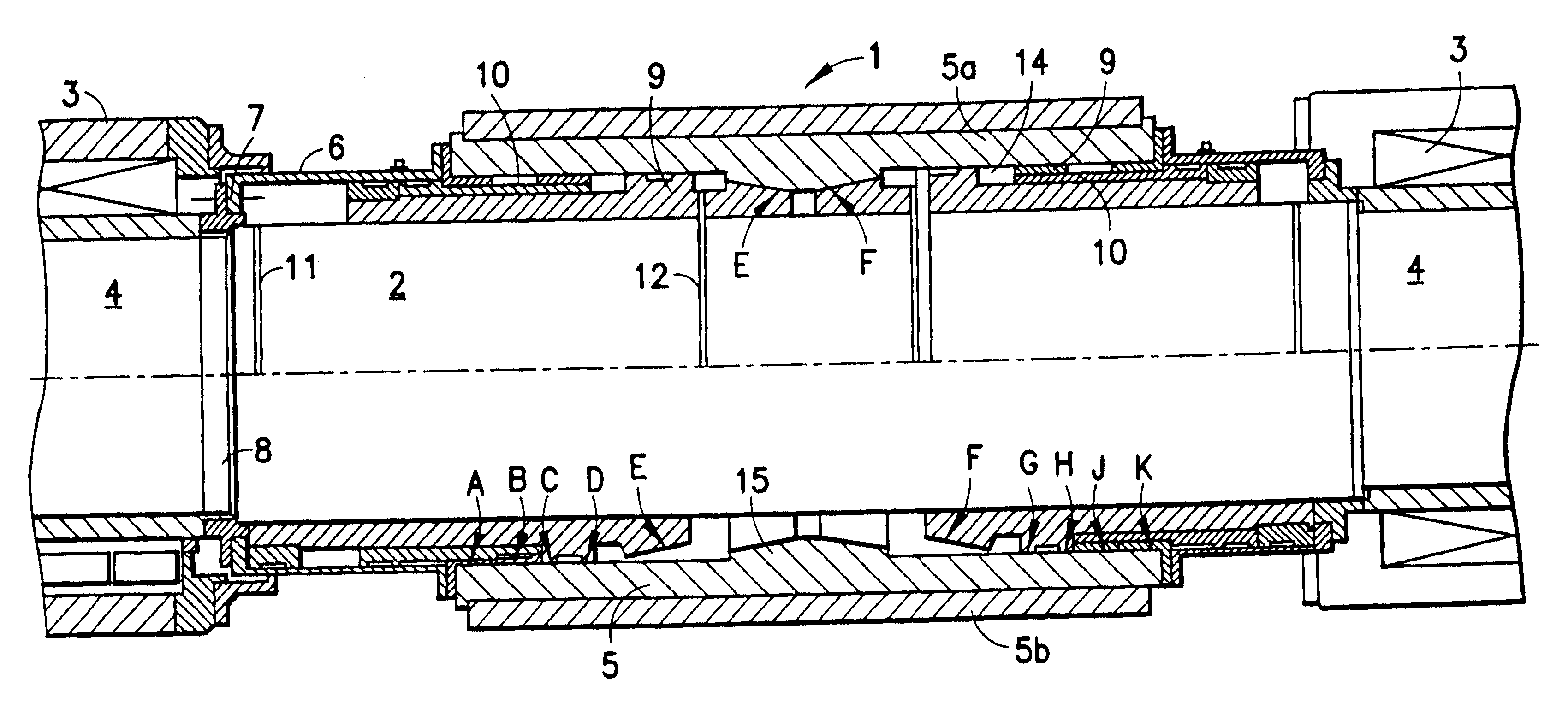
In the "soft" position of the same roll, a supporting distance of approximately 1350 mm is set between the supporting bearings. With corresponding dimensioning, the deflection in the barrel center of the roll, with a load of 4000 t, is approximately 6 mm. It can be seen from this example that the different deflections of the roll with the same load and different positions of the annular pistons make it possible to set at least two different crowns, it being possible for the precise regulation to take place via the working-roll bending used hitherto. Widening the invention by way of independently controllable annular pistons which can be displaced axially on the first-mentioned annular pistons allows any desired number of intermediate positions in which it is also possible to set the annular pistons, and thus the supporting bearings, non-symmetrically in relation to the roll center. For this purpose, use is made of means for regulating the quantity of oil supplied, which make it possible for the annular pistons to advance up to any desired intermediate position.
In accordance with this finding, it is proposed, by way of a further feature of the invention, that at least four, preferably ten to twelve supporting bearings on at least two to four annular pistons be distributed symmetrically over the length of the rolls, the spacings between adjacent supporting bearings in the central region of the roll being selected to be smaller than the spacings which increase in the direction of the border. The spacings which are smaller in the central region of the roll on account of the higher loading thus become larger in the direction of the border, as a result of which it is possible to achieve a harmonic deflection curve for the roll.
Moreover, calculations of the deflection values of the roll according to the invention show that, in the hard position, the roll only has 0.2 mm more deflection than a solid roll. This means that even the supporting roll assembled according to the invention from core roll and sleeve has sufficiently good rigidity.
In a favorable configuration of the invention, the sliding surfaces in the bores are nitrated and the annular pistons are provided with bronze surfaces on the outside, in order to improve the sliding properties and to minimize the wear. For the same reason, according to a further feature of the invention, it is proposed to use lubricating oil as the hydraulic fluid because, on the one hand, the pressures which are necessary for adjusting the annular pistons are low (approximately 30 bar) in relation to the pressures which are required by the solution according to the prior art and, on the other hand, the lubricating oil used promotes the sliding properties.

Problems solved by technology

Although these known systems meet the demand of the customers of new rolling mills, who would like, in addition to the working-roll bending, at least one further adjusting means for influencing the profile, the two systems are not suitable for being adjusted under load as well.
Ground-profile rollers are also disadvantageous because, in order to achieve the desired contours, high-outlay grinding is necessary, and the geometry of this grinding also has to be very precise.
Crossing of the rolls results in the disadvantage that the crossing angle of the rolls requires particular measures for a uniform angular speed, which rules out the use of normal cross-journal universal joint shafts for driving the rolls.
Added to this is the fact that the rolling-stock guidance poses problems; the rolling stock twists.
The wedges with a relatively small slope, however, tend to wedge in between roll core and roll sleeve, i.e. self-locking of said wedges occurs, and this self-locking is difficult to release under rolling force.

Method used


Image

  • Back-up or intermediate roller for producing a flat rolled product in a rolling mill
  • Back-up or intermediate roller for producing a flat rolled product in a rolling mill

Examples


Embodiment Construction

.

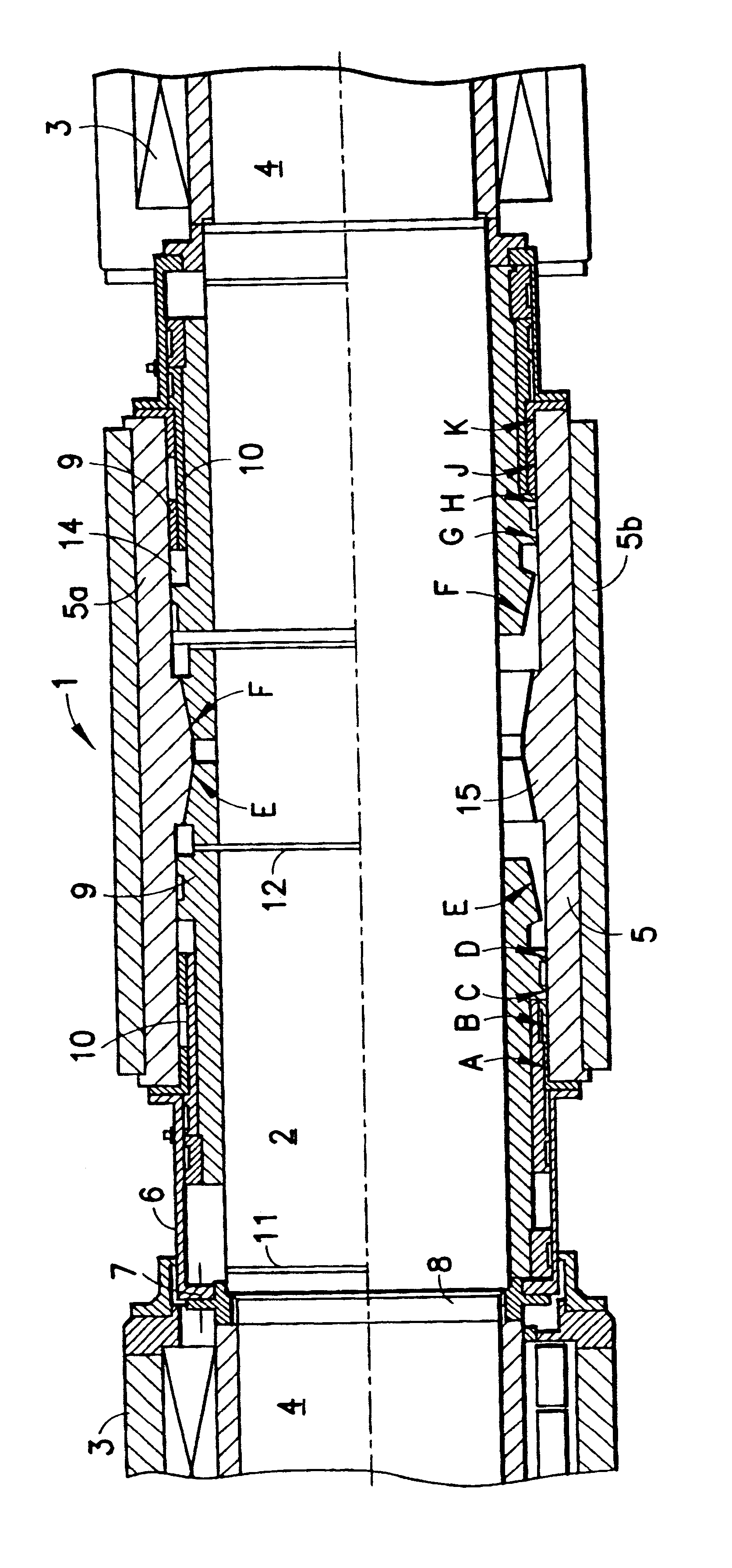
In the single figure of the drawing, 1 designates a supporting roll according to the invention, which comprises the roll core 2, the roll journals 4, which are mounted in indicated cylinder roller bearings 3, and the roll sleeve 5, which is connected in a rotationally fixed manner to the roll core 2. The sheath. 6 ensures that the roll sleeve 5 is carried along with the roll core 2, said sheath 6 engaging at 7 in a roll-journal toothing formation indicated at 8. In the example illustrated, the supporting roll 1 is provided with a two-part roll sleeve 5, which is made up of the basic part 5a and the exchangeable wear part 5b. Of course, it is also possible for the roll sleeve to be in one piece. Between the roll sleeve, which is designated 5 hereinbelow in order to simplify matters, and the roll core 2 are the annular pistons 9, and further annular pistons 10 arranged thereon. The two pistons 9, 10 are arranged such that they can be displaced axially independently of one another, it...


PUM

PropertyMeasurementUnit
Angleaaaaaaaaaa
Lengthaaaaaaaaaa
Displacementaaaaaaaaaa

Abstract

A supporting or intermediate roll in rolling mills for rolling flat rolling stock, in particular strip material, having a cylindrical roll core and a tubular sleeve which is connected in a rotationally fixed manner to said roll core, engages coaxially around the same and between which and the roll core there are arranged hydraulically axially displaceable supporting bodies which support the roll sleeve against the roll core. In this case, the supporting bodies are formed with at least two annular pistons, which are arranged symmetrically in relation to the roll center and are sealed in relation to the roll core and the inside of the roll sleeve, and include a plurality of annular supporting bearings, which are arranged on the outer circumference of the pistons, are spaced apart from one another in the longitudinal direction of the roll and against which the inner surface of the roll sleeve can be positioned.

Description

1. Field of the InventionThe invention relates to a supporting or intermediate roll in rolling mills for rolling flat rolling stock, in particular strip material. Such a roll comprises a cylindrical roll core and a tubular sleeve which is connected in a rotationally fixed manner to said roll core, engages coaxially around the same and between which and the roll core there are arranged hydraulically axially displaceable supporting bodies which support the roll sleeve against the roll core.2. Discussion of the Prior ArtThe profile and flatness control plays an important roll in modern hot strip mills. In this case, the negative and positive working-roll bending is the "classic" adjusting means, which allows a change in the roll gap even under load. Since, however, the conditions under which flat rolling stock is rolled are very different and width, thickness, profile and material change as well as the rolling speed and the rolling temperature, it is necessary, with the small batch siz...

Claims


Application Information

Patent Timeline
IPC IPC(8): B21B27/05B21B27/03B21B27/02
CPCB21B27/05
Inventor FIGGE, DIETERSCHWERDT, WILHELMQUITMANN, UWE
Owner SMS DEMAG AG
Learn More