Liquid disrupter with reduced recoil

a liquid disrupter and recoil technology, applied in the direction of gun mountings, small arms, firearms, etc., can solve the problems of destroying the video camera located on the robot, destroying the video camera, and often accidentally releasing the barrel from its suppor

Inactive Publication Date: 2002-06-25
PROPARMS
View PDF16 Cites 34 Cited by
  • Summary
  • Abstract
  • Description
  • Claims
  • Application Information

AI Technical Summary

Benefits of technology

It is an object of the present invention to provide a bomb disrupter with a controlled recoil effect.

Problems solved by technology

The problem associated with the above-described disrupter system is that the barrel will often be accidentally released brutally from its support on the robot to be backwardly projected, reactively under the counter-force or recoil of the explosive charge detonating inside the barrel and outwardly blasting the water.
Often, such a disrupter severely damages or completely destroys the rover carrying it, and may also damage the video camera located on the robot, or other expensive equipment located thereon In addition to replacement or repair costs of the thus damaged equipment, damaging the video camera also has the drawback of taking away the available means to readily visually inspect the results of the water blast immediately after it has occurred, to verify whether the bomb has effectively been deactivated.
In such a disrupter arrangement as in the 156' patent, the threaded connection constitutes a weak spot, since the threads will rapidly become stretched and deformed, under explosion borne air pressure loads, bringing structural fatigue and possible disrupter failure.
Accordingly, such a disrupter device has low durability and low operating safety levels.
As illustrated in FIG. 1, the boring diameter size would require such level of air pressure that the overall disrupter assembly would most likely disintegrate the first time it is used, due to its integrity being compromised, in particular due to stress applied about the threads linking the barrel, the plug flange and the device rear body portion.

Method used


Image

  • Liquid disrupter with reduced recoil
  • Liquid disrupter with reduced recoil
  • Liquid disrupter with reduced recoil

Examples


Embodiment Construction

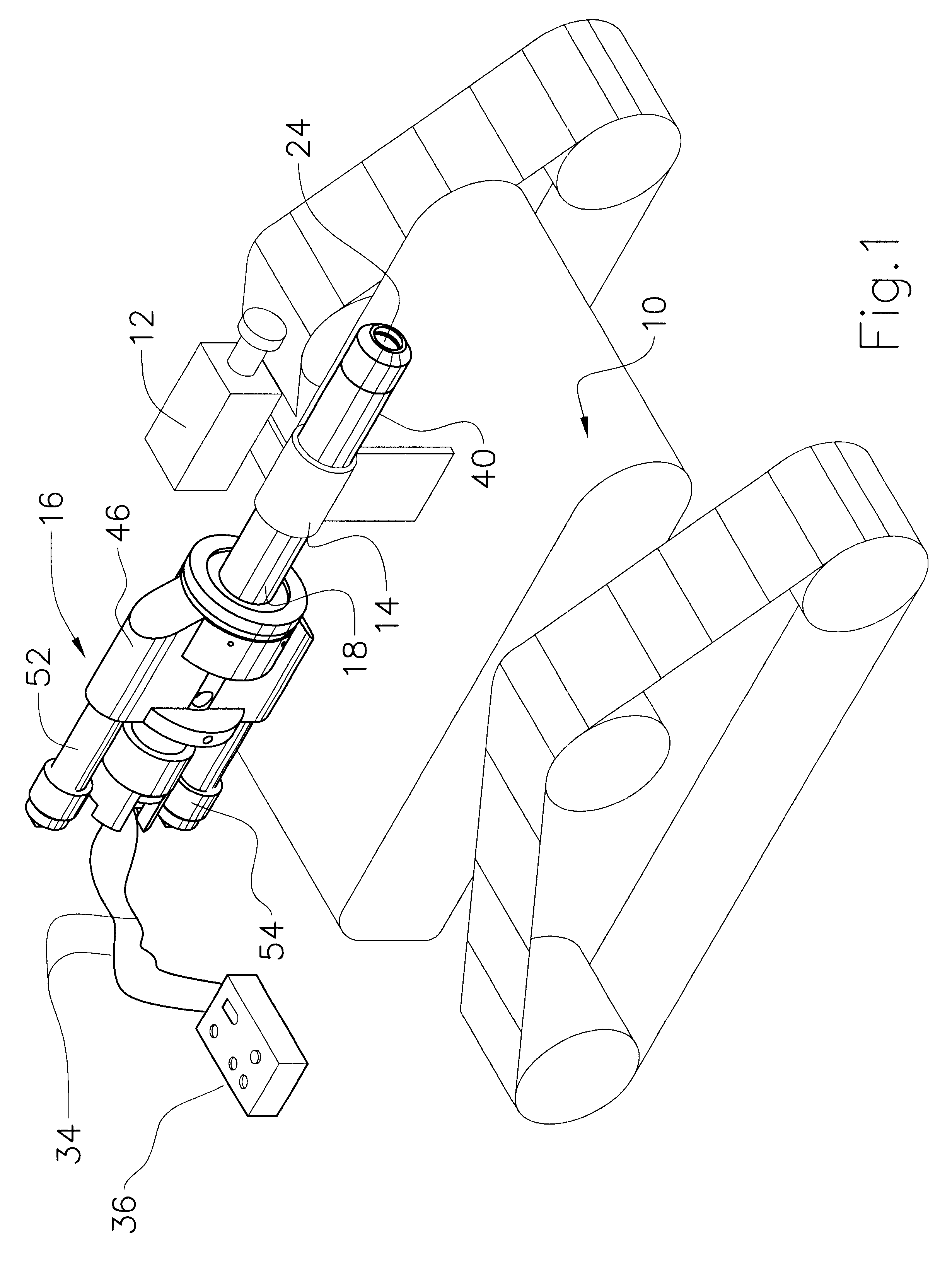
FIG. 1 schematically shows a small automated tracked robot 10 used by law enforcement agencies to carry bomb disrupters in an urban environment. Robot 10 is equipped with a video camera 12 allowing visual inspection of a bomb from a remote location, and with a disrupter support bracket 14 which securely holds a bomb disrupter 16 spacedly over the rover 10 according to the invention.

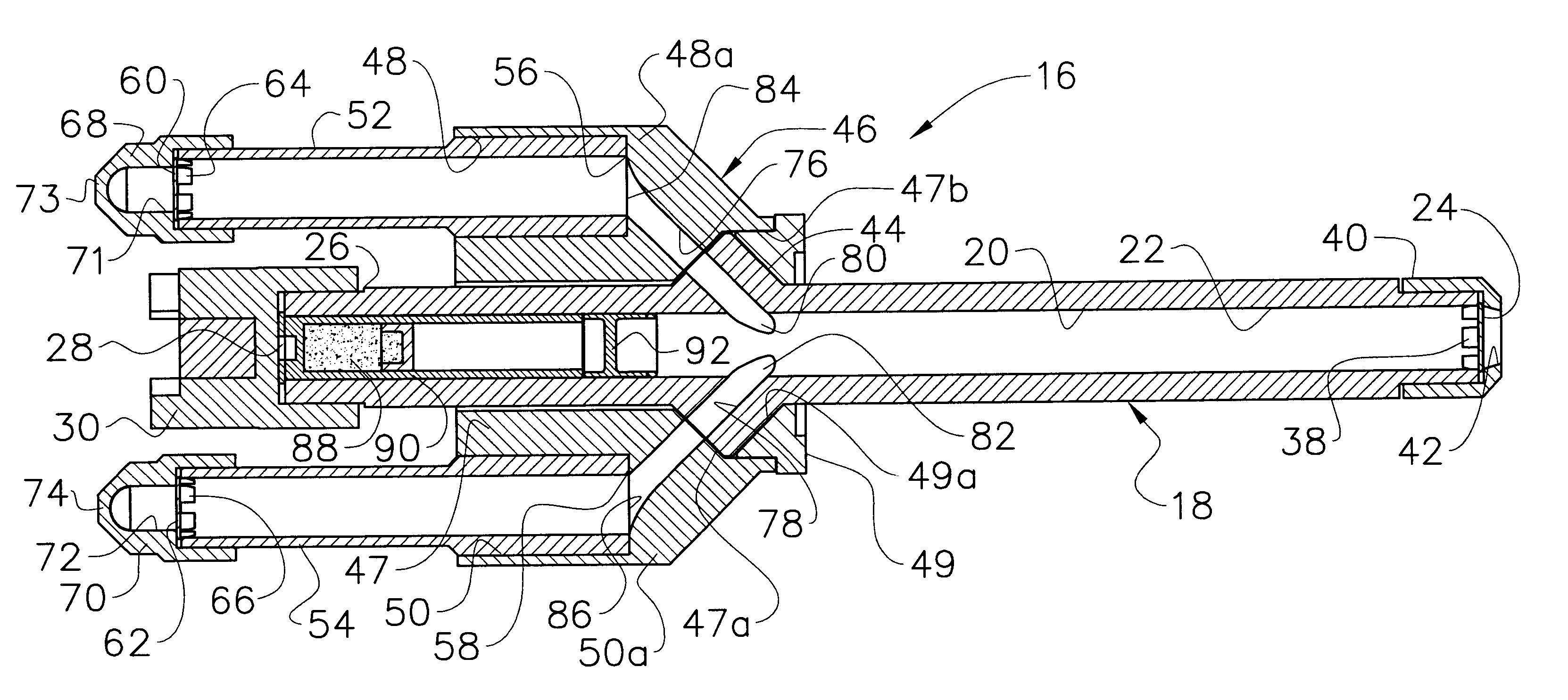
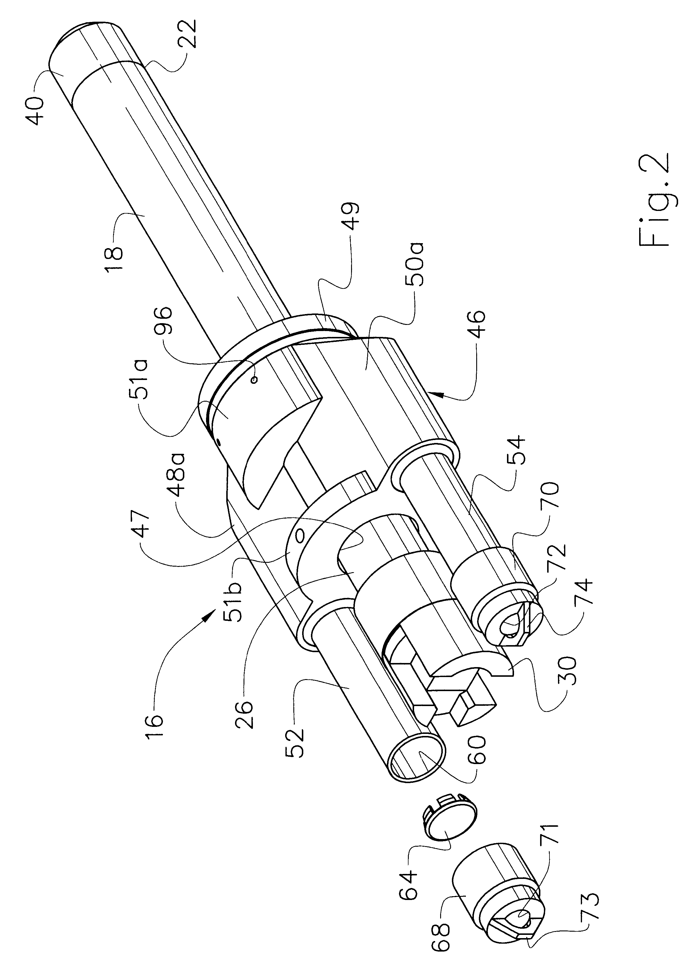
As shown in FIGS. 2, 3 and 4, disrupter 16 comprises a main elongated hollow barrel 18 which has a cylindrical inner chamber 20 and which defines a front end portion 22 having a front mouth opening 24, and a rear end portion 26 having a rear opening 28. The barrel rear opening 28 is releasably but securely closed with a screwable rear barrel cover 30 which is equipped with a trigger member in the form of wires 34 operatively connected to cover 30 and to a manually operable control panel 36 which can be remotely handled, as will be described hereinafter and as known in the art. Of course, wires 34 may be m...


PUM


Abstract

The disrupter (16) includes an elongated hollow barrel (18) having a cylindrical inner chamber (20), a closed rear (26) end and an opened front end (22), the latter closed with a front frangible seal (38). A channel member (46) partly surrounds an intermediate portion of the barrel, and is securely attached thereto. A pair of recoil channels (76, 78) extend from the barrel inner chamber, radially outwardly and rearwardly through the barrel and the channel member, and are linked to rearwardly oriented recoil tubes (52, 54) which have opened rear end portions (60, 62) closed with rear frangible seals (64, 66). In use, a cartridge (90) including an explosive charge (88) is to be inserted in the barrel inner chamber at its rear end, and the barrel, recoil channels and recoil tubes (52, 54) are to be filled with water. The frangible seals (38, 64, 66) prevent the water from leaking out of the disrupter while it is positioned near a bomb to be deactivated. A trigger (36) is linked to the disrupter, and more particularly to the cartridge, to remotely detonate the explosive charge. Upon the explosive charge being detonated, a portion of the water is propelled and ejected at high velocity out through the barrel front end, rupturing the front frangible seal, to puncture the bomb outer shell and deactivate the bomb inner detonating components. Another portion of the water is redirected through the side recoil channels and recoil tubes, rupturing the rear frangible seals, to be ejected rearwardly out of the disrupter. The recoil created by the detonation of the explosive charge which ejects the water through the barrel front end, is at least partially counteracted by the water being laterally and rearwardly redirected to be ejected rearwardly out through the recoil tubes. The recoil tubes have at their rear ends (60, 62) transverse blades (73, 74) for wide angle dispersal of the fluid jet being ejected rearwardly.

Description

The present invention relates to disrupter systems, and more particularly to a recoil controlled bomb disrupter.It is known to provide bomb disrupters which disrupt or deactivate the bombs by blasting a high-velocity water jet against the bomb. A disrupter of known configuration includes a main hollow cylindrical barrel having a closed rear end portion and a sealable opened front end mouth portion. A water-tight explosive charge or cartridge is loaded inside the barrel at the rear end thereof and the barrel is then filled with water before the front end of the barrel is closed with a frangible water-tight seal. The disrupter is carried towards the bomb to be deactivated, for example by means of an automated remote control rover which is equipped with a video camera which allows remote visual inspection of the bomb as the rover approaches same. The disrupter barrel front end mouth is oriented towards the bomb along a selected direction, and the explosive charge therein is then detona...

Claims


Application Information

Patent Timeline
Patent Type & Authority Patents(United States)
IPC IPC(8): F42B33/00F41A1/00F42B33/06F41A1/10F41B9/00
CPCF41A1/10F42B33/062F41B9/0046
Inventor ELSENER, JOSEF
Owner PROPARMS
Why Eureka
Try Eureka