Compact four-way waveguide power divider

a power divider and four-way technology, applied in the field of high frequency electromagnetic circuits and systems, can solve the problems of large structure and compact structure of structures

Inactive Publication Date: 2002-06-25
OL SECURITY LIABILITY CO
View PDF0 Cites 67 Cited by
  • Summary
  • Abstract
  • Description
  • Claims
  • Application Information

AI Technical Summary

Problems solved by technology

The disadvantage of such structures is therefore size.
This allows the input and output wav

Method used


Image

  • Compact four-way waveguide power divider
  • Compact four-way waveguide power divider
  • Compact four-way waveguide power divider

Examples


Embodiment Construction

Illustrative embodiments and exemplary applications will now be described with reference to the accompanying drawings to disclose the advantageous teachings of the present invention.

While the present invention is described herein with reference to illustrative embodiments for particular applications, it should be understood that the invention is not limited thereto. Those having ordinary skill in the art and access to the teachings provided herein will recognize additional modifications. applications, and embodiments within the scope thereof and additional fields in which the present invention would be of significant utility.

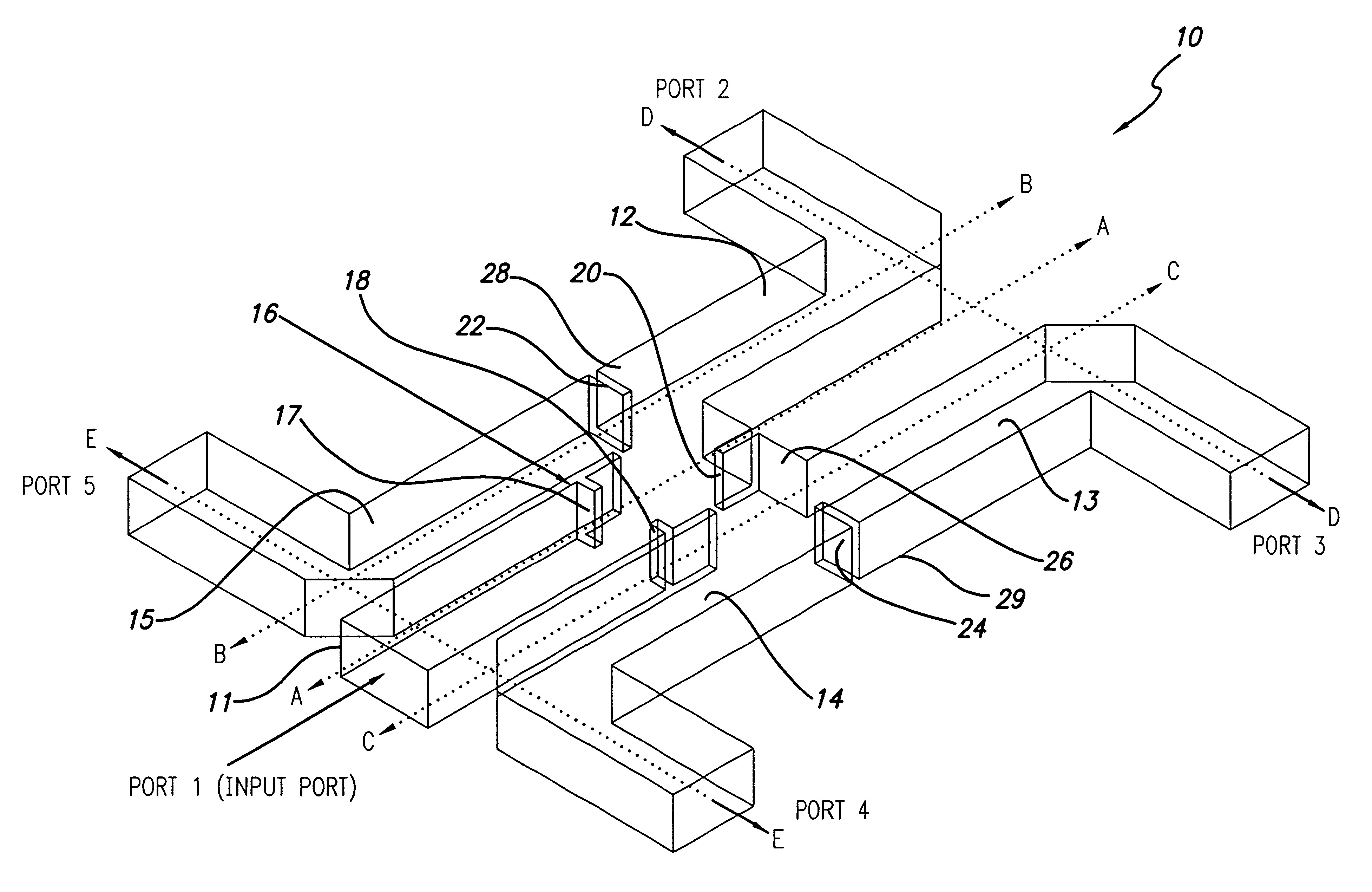
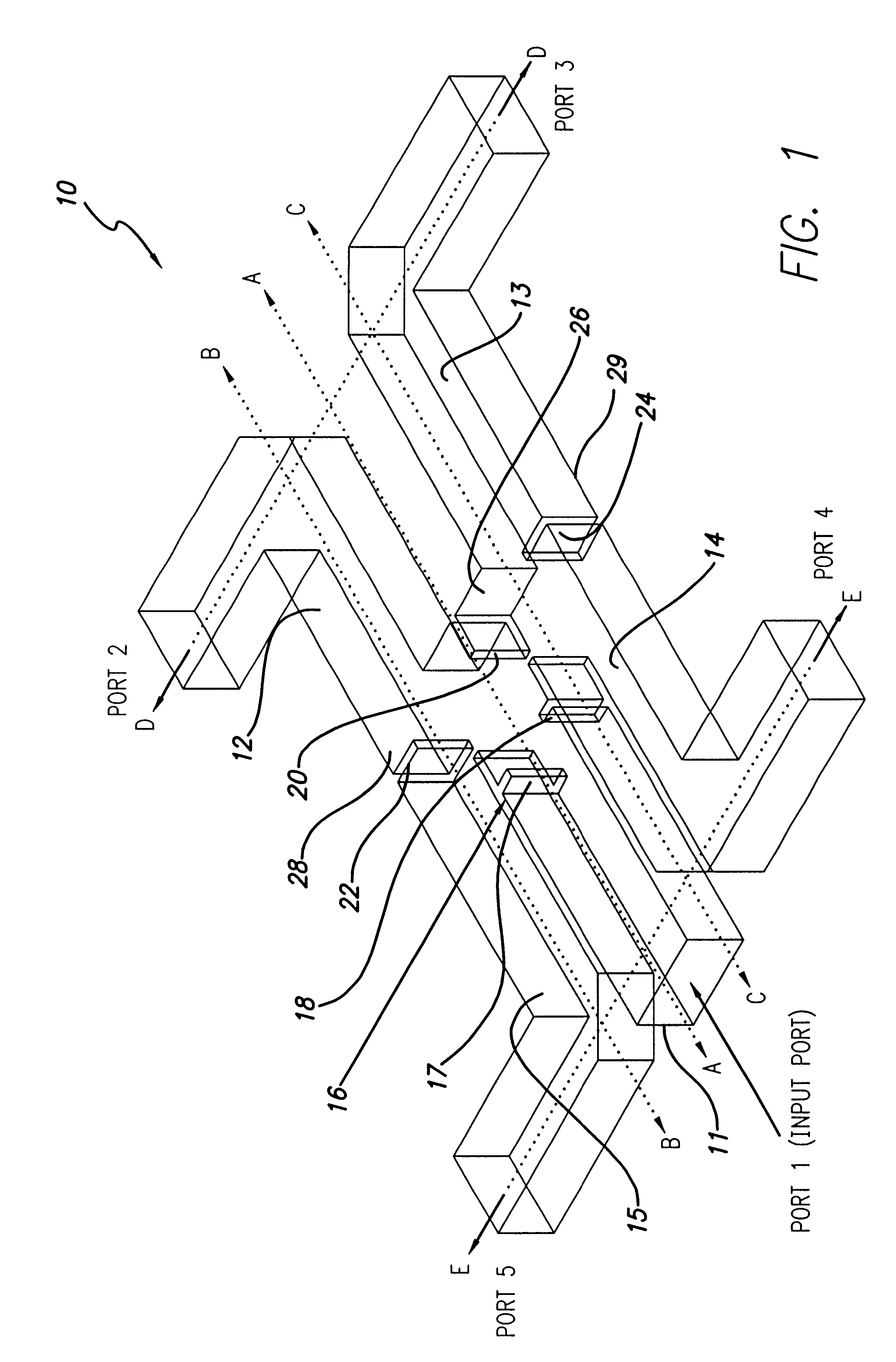
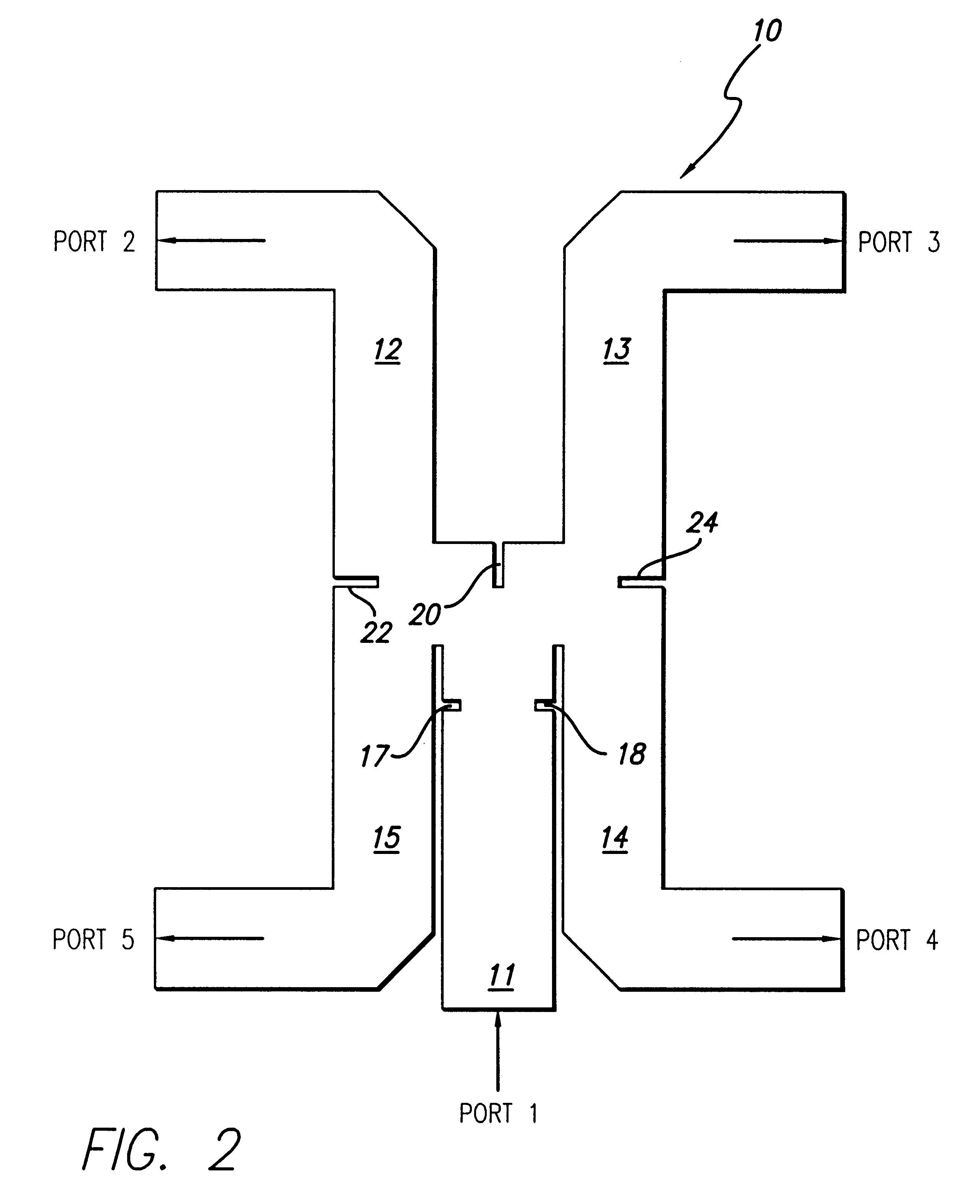
The present invention is a compact four-way waveguide power divider whose outputs have nearly equal amplitudes and phases. A realization of this invention at 35 GHz is shown in FIG. 1.

FIG. 1 is an isometric view of a compact four-way waveguide power divider constructed in accordance with the teachings of the present invention. The power divider 10 includes a fir...


PUM


Abstract

A compact four-way waveguide power divider (10). The inventive power divider (10) includes an input waveguide (11) that terminates at a junction with two adjacent waveguides on opposite sides of the input waveguide. On the opposite side of the junction is a conducting wall into which is built an inductive septum (20). The inductive septum (20) serves to partially match the input impedance of the structure. Second and third inductive septums (22 and 24) are also built into the output arms of the power divider (10). The purpose of the second and third septums (22 and 24) is twofold. In addition to partially matching the power divider's input impedance, the positions of the second and third septums (22 and 24) can be adjusted to equalize the power division between the output arms. Hence, the waves exiting the four output arms of the power divider have highly equalized amplitudes and phases. Further, the phases at the output ports are equalized by adjusting the lengths of the output arms. The use of offset inductive septums (22 and 24) in the output arms to achieve equalized power division allows the input and output waveguides to be placed in very close proximity, resulting in an extremely compact structure.

Description

1. Field of the InventionThe present invention relates to high frequency electromagnetic circuits and systems. More specifically, the present invention relates to waveguide power dividers for use with radar systems.2. Description of the Related ArtHigh frequency (e.g. microwave) circuits and systems typically require a division of power between two or more paths. Radar duplexers, for example, require an equal division of input power among the four output arms while simultaneously minimizing the phase difference between any two arms and the amount of reflected power. A duplexer is a device that splits microwave (radar) energy between two or more paths.Conventional four-way power dividers that operate between 1 and 140 GHz are typically constructed from three two-way power dividers. Two-way power dividers automatically provide equal power division via symmetry and typically use a single inductive septum or post to match the input impedance.To ensure equal division of power and high re...

Claims


Application Information

Patent Timeline
IPC IPC(8): H01P5/12
CPCH01P5/12
Inventor CROUCH, DAVID D.GIANCOLA, VINCENTBROWN, KENNETH W.
Owner OL SECURITY LIABILITY CO
Why Eureka
Try Eureka