Single-port multi-resonator acoustic resonator device

a resonator device and single-port technology, applied in the field of acoustic devices, can solve the problems of general unwanted or spurious resonance and are not used

Active Publication Date: 2006-11-21
QORVO US INC
View PDF4 Cites 62 Cited by
  • Summary
  • Abstract
  • Description
  • Claims
  • Application Information

AI Technical Summary

Problems solved by technology

Such resonances are generally unwanted or spurious and are not used, except in some specialized applications.

Method used


Image

  • Single-port multi-resonator acoustic resonator device
  • Single-port multi-resonator acoustic resonator device
  • Single-port multi-resonator acoustic resonator device

Examples


first embodiment

[0058]the present invention is illustrated in FIG. 5 as resonator device 200, composed of transducer / resonator 201, mechanical resonator 203, and acoustic coupler 202, all of which elements are integrated in a vertically stacked, unitary assembly. Transducer / resonator 201 is primarily composed of piezoelectric region 211 and the associated electrodes 210 and 212, respectively attached at interfaces 213, 214. The resonator portion of transducer-resonator 201 also necessarily includes a portion of the acoustic coupler 202 in effect as herein described. Transducer 201 is electrically driven by an electrical signal applied across electrodes 210 and 212. Transducer / resonator 201 need not be restricted in composition to the simple three layer structure of electrode, piezoelectric layer and electrode, illustrated in FIG. 5, but may be composed of other more complex structures that exhibit a single acoustic resonance at its fundamental resonant frequency as described, for example, in U.S. P...

second embodiment

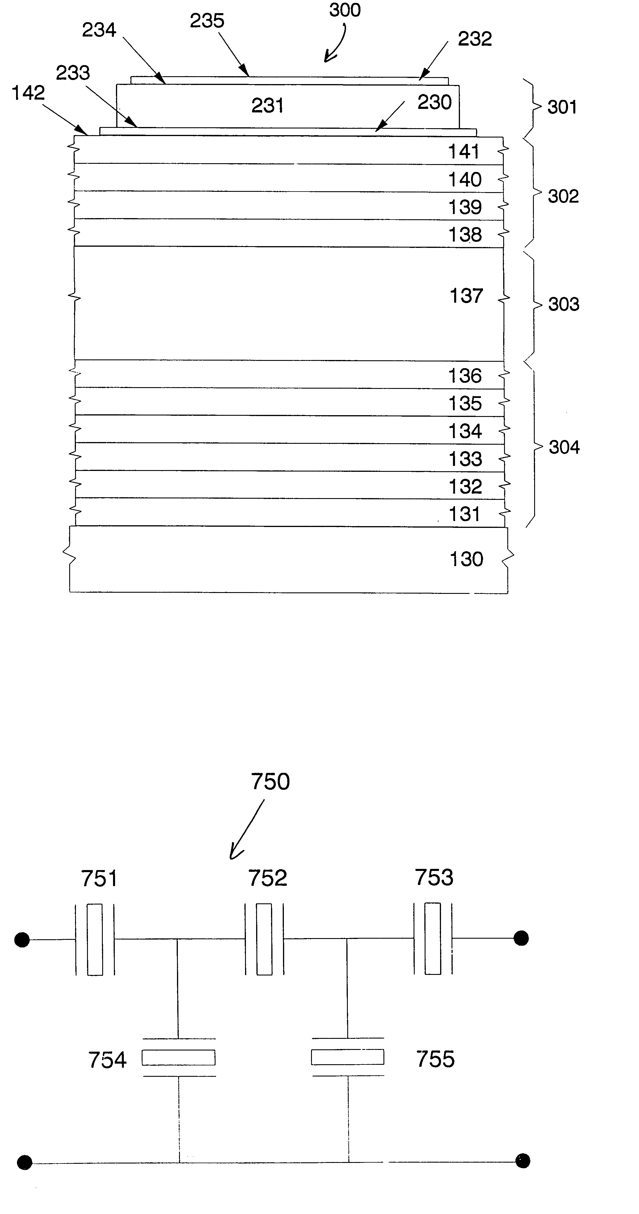
[0060]the invention is illustrated in FIG. 6 as resonator device 300 to which reference is made. In this embodiment resonator device 300 is formed in an integral assembly with or attached to a substrate 130 through acoustic isolator 304. Resonator device 300 is composed of transducer / resonator 301, acoustic coupler 302, formed of layers 138, 139, 140 and 141, mechanical resonator 303, and isolator 304 formed as a vertical stack atop substrate 130 in an integral, one piece assembly. Isolator 304 is formed of multiple layers of solid sound conducting material, 131, 132, 134, 135, 136, and 138.

third embodiment

[0061]the invention, resonator device 400, is illustrated in FIG. 7 to which reference is made. Resonator device 400 is composed of a vertically arranged stack of layers containing mechanical resonator 403, acoustic coupler 404, transducer / resonator 401, isolator 402, and substrate 550 formed in a stacked, one-piece integral assembly. In this configuration mechanical resonator 403, formed of a slab or block of solid vibration conducting medium, is situated as the top portion of resonator device 400 to have the top surface 565 accessible. Transducer / resonator 401 may be fabricated in different arrangements of varying complexity, but, at a minimum, includes a piezoelectric region 411 and electrodes 410 and 412 to which electrical signals may be applied to drive the resonator device. Acoustic isolator 402 may be composed of one or more layers of material, such as layers 551 through 556, that produces a sufficient acoustic isolation between transducer 401 and substrate 550 inhibiting or...


PUM


Abstract

A single port multi-resonator acoustic resonator device (200, 300, 400, 490) possesses an input impedance that exhibits precisely designed electrical resonances. The device contains at least three parts: a transducer / resonator (201, 301, 401. 491) used both to interface to an external electrical circuit and to transform electrical energy into mechanical (i.e. acoustic) vibrations (and vice versa), and also function as a resonator; a mechanical (i.e. acoustic) resonator (203, 303, 460, 480) and an acoustic coupler (202, 302, 404, 494) that controls the acoustic interaction between the transducer / resonator and the mechanical resonator.

Description

FIELD OF THE INVENTION[0001]This invention relates to acoustic devices and, more particularly, to acoustic bulk-wave piezoelectric resonator devices capable of exhibiting complex resonance properties and to frequency filters formed with those resonators. The resonator devices are useful over a wide range of frequencies and are particularly useful for operation at microwave frequencies.BACKGROUND[0002]Communications systems have need for components, such as resonators and filters, that control frequency generation or that limit the range of frequencies used in the systems. Resonators are not only formed of electrical inductor and capacitor circuits, but can also be electromechanical in nature, such as quartz crystals, surface acoustic wave devices, or thin film bulk acoustic resonators. Frequency filters also may be based upon that core resonator technology. Resonators exhibiting multiple resonances at nearby frequencies within a single structure would be particularly useful in frequ...

Claims


Application Information

Patent Timeline
Patent Type & Authority Patents(United States)
IPC IPC(8): H03H9/15H03H9/54
CPCH03H9/175H03H9/586
Inventor LAKIN, KENNETH MEADE
Owner QORVO US INC
Why Eureka
Try Eureka