Wireless power transmitter, wireless power receiver, and power transmission method of wireless power transmitting system

a wireless power transmitter and wireless power technology, applied in the direction of transmission, circuit arrangement, inductance, etc., can solve the problem of degrading power transmission efficiency, and achieve the effect of efficiently detecting the coupling state and active controlling the impedance of the load sid

Active Publication Date: 2013-08-22
SCRAMOGE TECH LTD
View PDF17 Cites 64 Cited by
  • Summary
  • Abstract
  • Description
  • Claims
  • Application Information

AI Technical Summary

Benefits of technology

[0008]The embodiment provides a wireless power transmitter capable of actively controlling impedance of a load side by efficiently detecting a coupling state betwee

Problems solved by technology

However, since impedance of a load side connected to a receiver side or inductance of a coil of the receiver side is fixed,

Method used


Image

  • Wireless power transmitter, wireless power receiver, and power transmission method of wireless power transmitting system
  • Wireless power transmitter, wireless power receiver, and power transmission method of wireless power transmitting system
  • Wireless power transmitter, wireless power receiver, and power transmission method of wireless power transmitting system

Examples


Embodiment Construction

[0045]Hereinafter, embodiments will be described in detail with reference to accompanying drawings so that those skilled in the art can easily work with the embodiments.

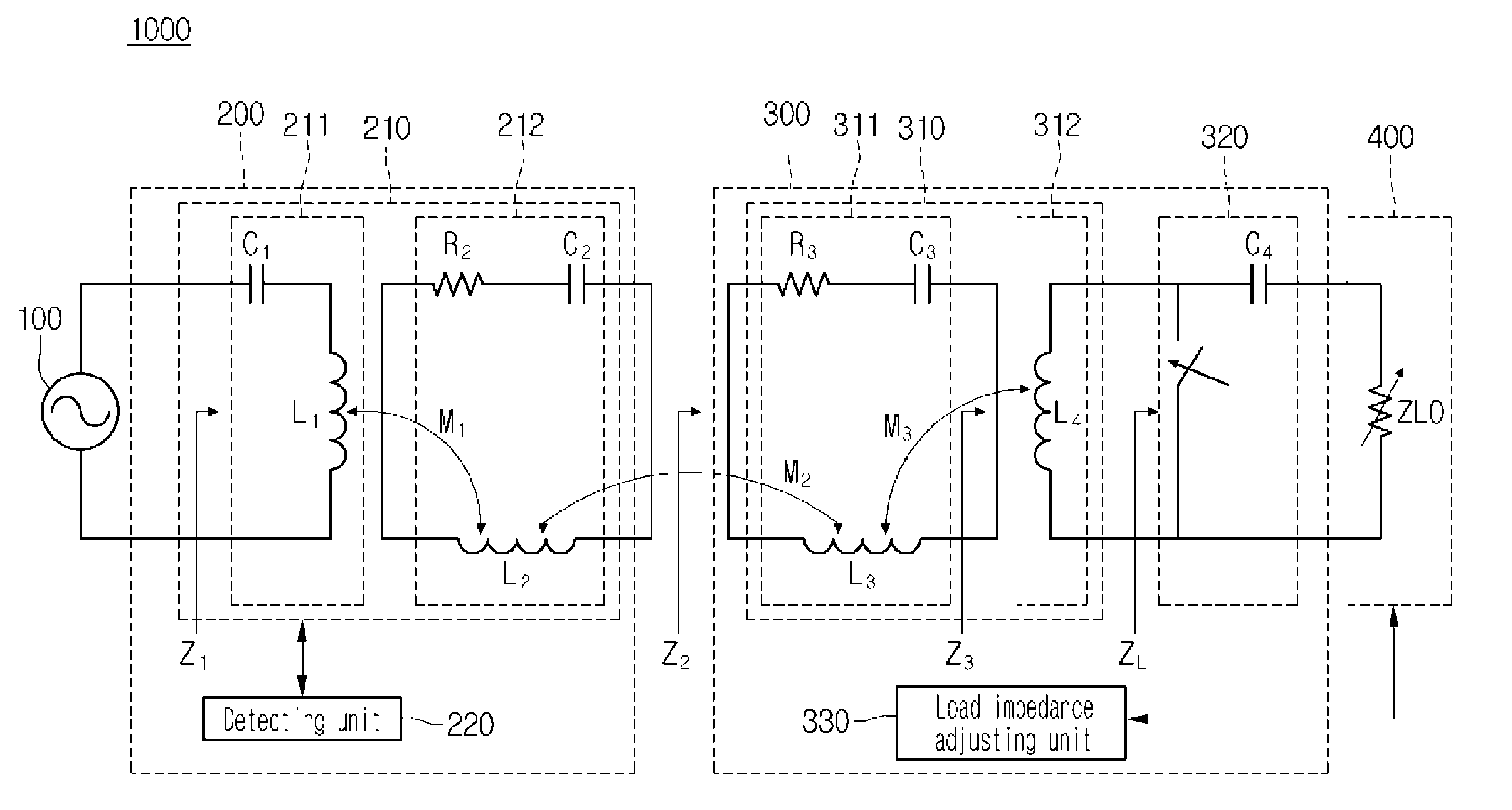
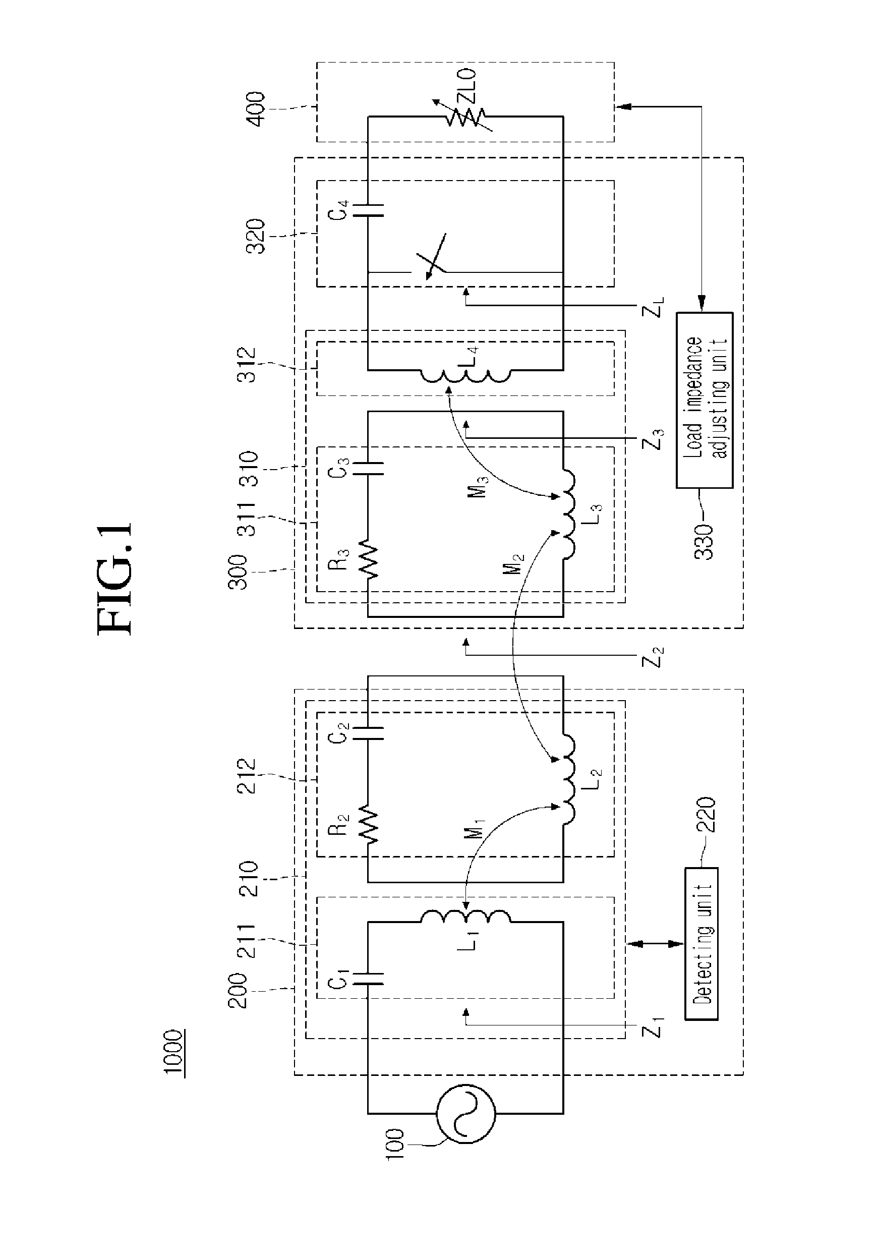
[0046]FIG. 1 is a diagram showing a configuration of a resonant wireless power transmitting system 100 according to the embodiment.

[0047]Referring to FIG. 1, the wireless power transmitting system 1000 may include a power source 100, a wireless power transmitter 200, a wireless power receiver 300, and a load side 400.

[0048]The wireless power transmitter 200 may include a transmitting unit 210 and a detecting unit 220.

[0049]The transmitting unit 210 may include a transmission induction coil unit 211 and a transmission resonance coil unit 212.

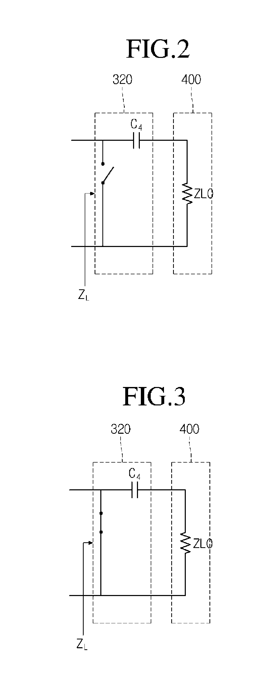
[0050]The wireless power receiver 300 may include a receiving unit 310, an output impedance varying unit 320, and a load impedence adjusting unit 330.

[0051]The receiving unit 310 may include a reception resonance coil unit 311 and a reception induction coil unit 312.

[0052]The powe...


PUM


Abstract

A wireless power transmitter for transmitting power to a wireless power receiver in a wireless scheme includes a transmitting coil configured to transmit power, which is supplied by a power source, to a receiving coil of the wireless power receiver using resonance; and a detecting unit configured to detect a coupling state between the transmitting coil and the receiving coil using an input impedance of the wireless power transmitter.

Description

CROSS-REFERENCE TO RELATED APPLICATIONS[0001]This application claims the benefit under 35 U.S.C. §119 of Korean Patent Application Nos. 10-2012-0016237, filed Feb. 17, 2012 and 10-2012-0023329, filed Mar. 7, 2012, which are hereby incorporated by reference in their entirety.BACKGROUND[0002]The embodiment relates to a wireless power transmitter, a wireless power receiver, and a power transmission method of a wireless power transmission system.[0003]A wireless power transmission or a wireless energy transfer refers to a technology of wirelessly transferring electric energy to desired devices. In the 1800's, an electric motor or a transformer employing the principle of electromagnetic induction has been extensively used and then a method for transmitting electrical energy by irradiating electromagnetic waves, such as radio waves or lasers, has been suggested. Actually, electrical toothbrushes or electrical razors, which are frequently used in daily life, are charged based on the princi...

Claims


Application Information

Patent Timeline
IPC IPC(8): H04B5/00
CPCH04B5/0037H02J17/00H02J5/005H04B5/0087H02J50/12H02J50/80
Inventor BAE, SU HO
Owner SCRAMOGE TECH LTD
Why Eureka
Try Eureka