Electric potential sensor

a potential sensor and electric current technology, applied in the field of electric potential sensors, can solve the problem of not enhancing the signal-to-noise ratio by this technique, and achieve the effect of high-quality signal measuremen

Active Publication Date: 2011-11-08
THE UNIV OF SUSSEX
View PDF5 Cites 63 Cited by
  • Summary
  • Abstract
  • Description
  • Claims
  • Application Information

AI Technical Summary

Benefits of technology

[0010]The present invention seeks to overcome the problems described above and to provide a novel electric potential sensor, which is capable of highly accurate signal measurement.
[0011]The present invention, at least in the preferred embodiments described below, also seeks to provide an electric potential sensor in which the signal to noise ratio is significantly enhanced.
[0017]input impedance enhancing means for providing a high input impedance to the sensor amplifier for increasing the sensitivity of the electrode to reduced electric potentials; and
[0018]feedback means for applying a coherent feedback signal to the input of the sensor amplifier for enhancing the signal to noise ratio of the sensor.
[0020]In contrast with the usual practice for electrodynamic sensors, the feedback signal is not a broadband signal derived directly from the output of the sensor but is a coherent signal made available for feedback, and this significantly improves the signal to noise ratio.
[0026]The invention is also applicable in situations where the sensor is designed to drive or excite a sample being measured for generating a measurement signal for supply to the amplifier for amplification and output, and where it is desirable to eliminate charging of the sample and maintain a minimum signal on the sample. An example of this would be in microscopic applications in which a large electric field could damage or destroy a small semi-conducting device, or the surface of a sample, being measured.

Problems solved by technology

Although neutralisation may be used to increase dramatically the input impedance of the electrodynamic sensor of FIG. 1, as described in International Patent Application number WO 03 / 048789, the signal to noise ratio is not enhanced by this technique since the noise present at the sensor output is fed back to the sensor input.
One example of this is where problems caused by relative motion of the sample and the sensor need to be minimised.

Method used


Image

  • Electric potential sensor
  • Electric potential sensor
  • Electric potential sensor

Examples


Embodiment Construction

Prior Art

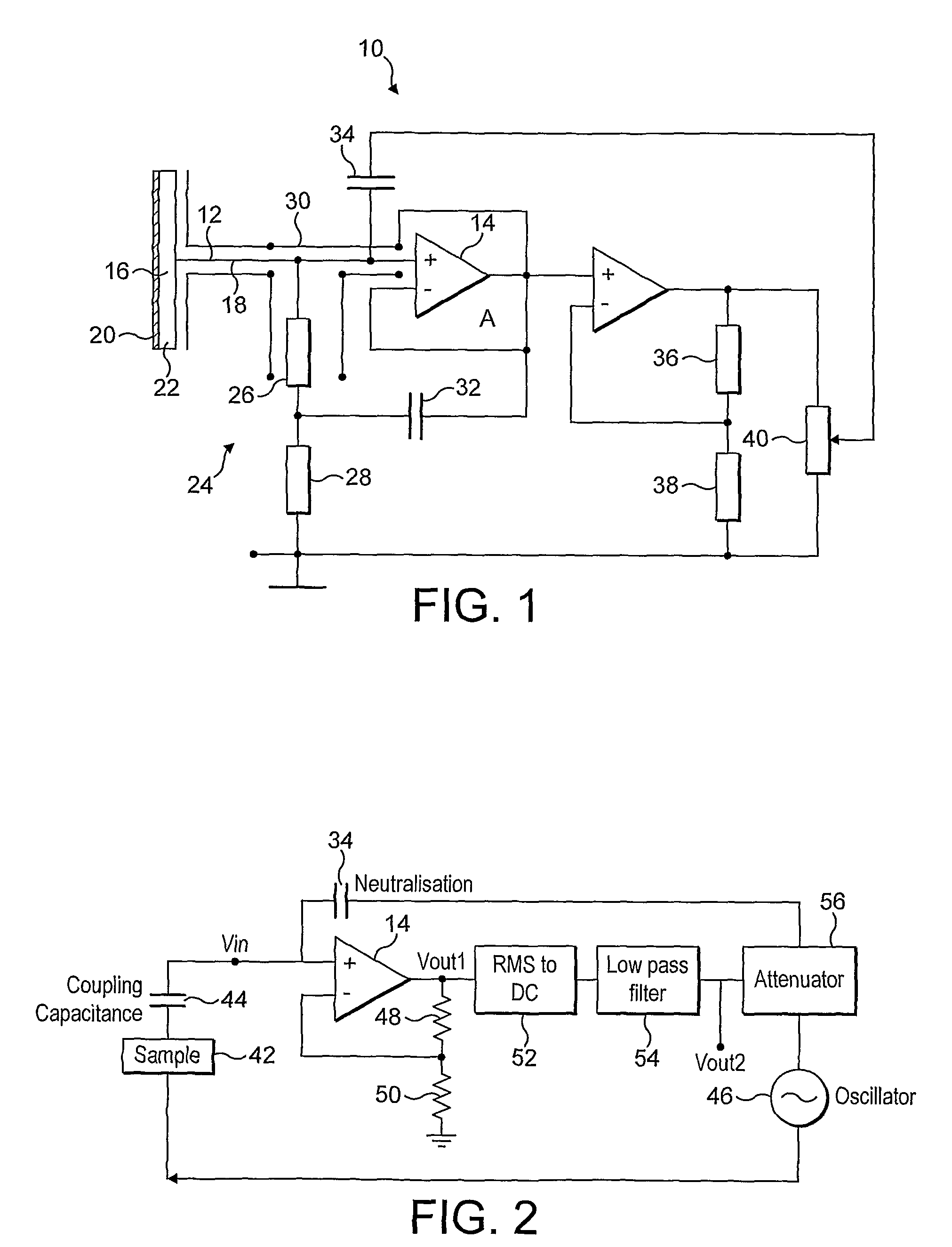
[0034]Referring to FIG. 1, an electrodynamic sensor as disclosed in International Patent Application No. WO 03 / 048789 will first be described.

[0035]As shown in FIG. 1, an eletrodynamic sensor 10 according International Patent Application number WO 03 / 048789 comprises a detection electrode 12 connected to the non-inverting input of a sensor amplifier 14. In use, the detection electrode 12 supplies a measurement signal as input to the sensor amplifier 14, which supplies an amplified detection signal as output.

[0036]The detection electrode 12 includes an electrode disc 16 mounted on a conductive stem 18, the electrode disc 16 comprising a surface oxide layer 20 on a substrate 22. The sensor amplifier 14 has a fixed input resistance 24, provided by two resistors 26, 28, connected between the electrode 12 and the non-inverting input of the amplifier 14, to provide a steady input bias current to the amplifier 14. In practice, the input resistor 24 will generally have a high resis...


PUM


Abstract

The invention provides an electric potential sensor including, at least one detection electrode arranged for capacitive coupling with a sample under test and for generating a measurement signal, and a sensor amplifier adapted to receive the measurement signal as input and to supply an amplified detection signal as output. An input impedance enhancing element provides a high input impedance to the sensor amplifier for increasing the sensitivity of the electrode to reduced electric potentials, and a feedback element applies a coherent feedback signal to the input of the sensor amplifier for enhancing the signal to noise ratio of the sensor.

Description

FIELD OF THE INVENTION[0001]The present invention concerns electric potential sensors for use for the measurement of potentials in a variety of applications, including for example the fields of medical applications and microscope applications, such as microscopic imaging and spectrum analysis, as well as nuclear magnetic resonance (NMR) applications, such as NMR imaging and spectroscopy.BACKGROUND TO THE INVENTION[0002]In order to create a sensitive electrodynamic measuring device, it is customary to provide a high input impedance and thereby reduce the power of the input signal required to operate the device. However, electronic circuits with a very high input impedance tend to be unstable, and so practical devices are usually a compromise between achieving the necessary degree of sensitivity, providing the desired input impedance and ensuring an acceptable degree of stability.[0003]In International Patent Application No. WO 03 / 048789, an electrodynamic sensor is disclosed in which...

Claims


Application Information

Patent Timeline
Patent Type & Authority Patents(United States)
IPC IPC(8): G01R19/00G01R27/26
CPCG01R33/323G01R15/165A61B5/0408A61B5/0478G01R19/0023A61B5/25A61B5/291A61B5/262
Inventor PRANCE, ROBERTHARLAND, CHRISTOPHER
Owner THE UNIV OF SUSSEX
Why Eureka
Try Eureka