Method for phototyping parts from sheet metal

a technology of sheet metal and phototype, which is applied in the direction of forging/pressing/hammering apparatus, shaping tools, handling devices, etc., can solve the problems of increasing the overall time required to construct the prototype, the inability to use the bending brake, and the cost of temporary stamping dies, which are less expensive than production dies, and achieves the effect of convenient bending

Inactive Publication Date: 2002-07-02
3 DIMENSIONAL SERVICES
View PDF7 Cites 77 Cited by
  • Summary
  • Abstract
  • Description
  • Claims
  • Application Information

AI Technical Summary

Benefits of technology

In practice, it has been found that a sheet metal blank up to 1/4 of an inch thick ha...

Problems solved by technology

As the complexity and number of the bends increase for the part, a bending brake cannot be used since the shape of the part interferes with the operation of the bending brake.
Such temporary stamping dies, while les...

Method used


Image

  • Method for phototyping parts from sheet metal
  • Method for phototyping parts from sheet metal

Examples


Embodiment Construction

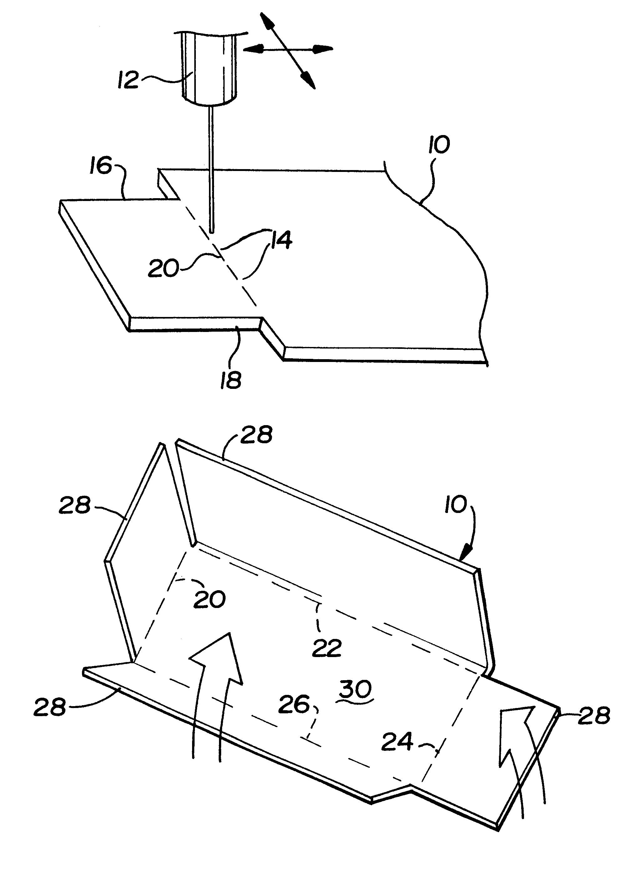
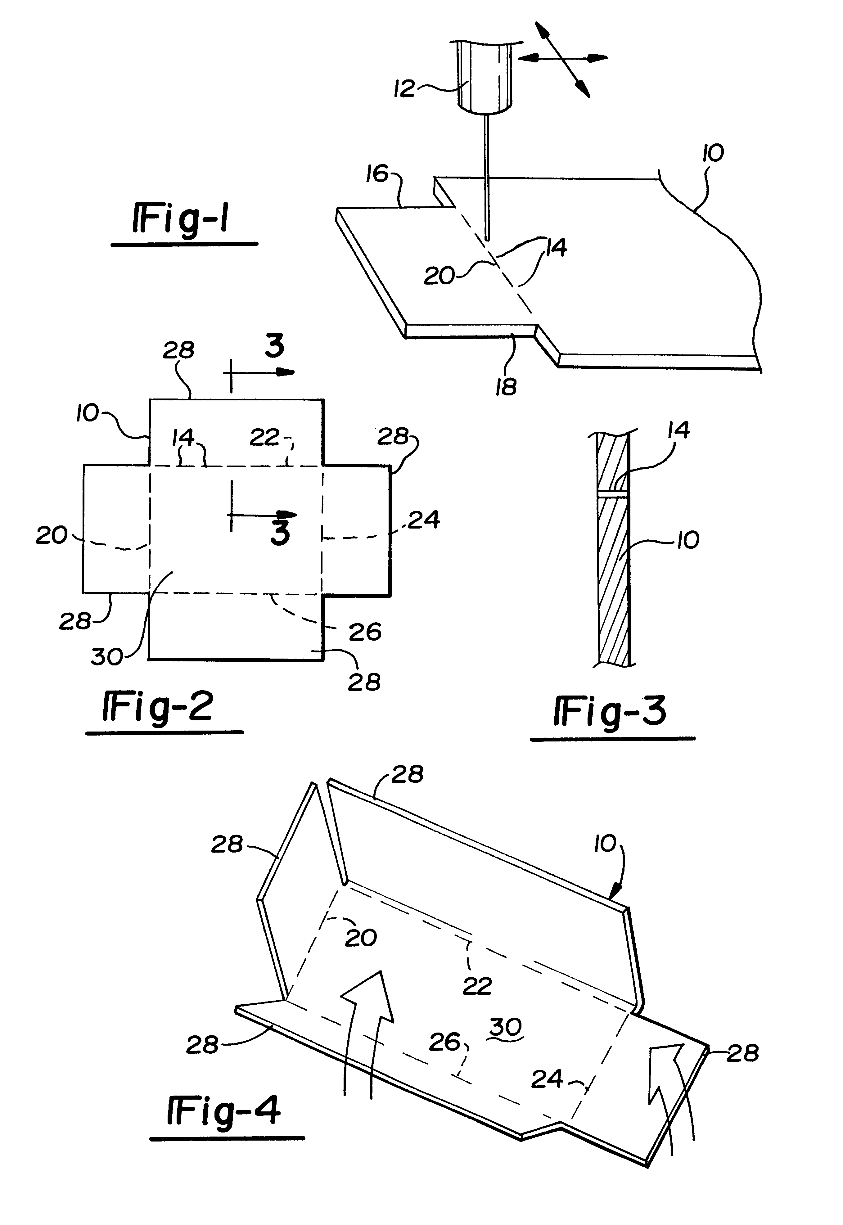
With reference first to FIGS. 1 and 2, a sheet metal blank 10 for forming a prototype is there shown. The sheet metal blank 10 is flat and may be up to 1 / 4 inch thickness. The shape of the sheet metal blank 10 shown in the drawing is for illustration purposes only. In practice, the sheet metal blank 10 may be of any desired shape, including more complex shapes.

Referring now particularly to FIG. 1, a laser 12 is preferably used to form a plurality of longitudinally aligned slots 14 through the sheet metal blank 10. The longitudinally aligned slots 14 extend between two edges 16 and 18 of the sheet metal blank 10 thus forming a bend line 20 between the edges 16 and 18 of the sheet metal blank 10.

With reference now particularly to FIG. 2, the sheet metal blank 10 is there illustrated having four bend lines 20, 22, 24 and 26 thus delineating four outwardly extending tabs 28 from a main body portion 30 of the sheet metal blank 10.

Referring now to FIGS. 2 and 3, the length of the slots 14...


PUM

PropertyMeasurementUnit
Lengthaaaaaaaaaa

Abstract

A method for prototyping parts from a sheet metal blank in which the sheet metal has at least two spaced edges. The method includes the step of forming a plurality of longitudinally aligned slots through the sheet metal blank to form a bend line extending between two spaced edges on the sheet metal blank. The slots are preferably formed by laser cutting. The sheet metal blank is then bent along the bend line to form the prototype.

Description

I. Field of the InventionThe present invention relates to a method for prototyping parts from sheet metal.II. Description of the Prior ArtIn many industrial applications, it is necessary to prototype parts from sheet metal before production stamping dies are made. Such prototypes enable the manufacturer to ensure that the part, when finally manufactured on a production basis, will meet the design and assembly requirements of the production part.There have been a number of previously known methods for constructing prototypes from sheet metal. One such method has been to bend the sheet metal along the desired bend line using a bending brake. The use of a bending brake, however, is suitable only for very simple parts. As the complexity and number of the bends increase for the part, a bending brake cannot be used since the shape of the part interferes with the operation of the bending brake.Consequently, in order to construct prototypes from sheet metal for more complex shapes, it has b...

Claims


Application Information

Patent Timeline
IPC IPC(8): B23K26/36B23K26/38B23K26/00B21D51/52B21D51/16
CPCB21D51/52B23K26/367B23K26/383B23K2201/18B23K26/364B23K26/384B23K2101/18
Inventor CROSWELL, EDWARD M.
Owner 3 DIMENSIONAL SERVICES
Why Eureka
Try Eureka