Gas-insulated circuit-breaker with an integrated electronic current transformer

a technology of electronic current transformer and circuit breaker, which is applied in the field of circuit breakers, can solve the problems of high transformer maintenance costs, and achieve the effect of reducing the ground area occupied and reducing the maintenance costs of the current transformer

Inactive Publication Date: 2002-07-02
ALSTOM TECH LTD
View PDF8 Cites 7 Cited by
  • Summary
  • Abstract
  • Description
  • Claims
  • Application Information

AI Technical Summary

Benefits of technology

An object of the invention is to propose a circuit-breaker of the first kind as defined above that enables maintenance costs of the current transformer to be reduced and also reduces the ground area occupied by the circuit-breaker. Another object is to provide a current transformer arranged in modular manner so as to make to possible for the transformer to be mounted in a plurality of different configurations independently of the configuration of the circuit-breaker (column circuit-breaker or T-configuration).
The secondary can thus be associated with an optical or an optoelectronic circuit placed close thereto in air and subjected to the high voltage electrical potential, such a circuit being connectable to devices disposed on the ground by means of optical fibers. Transformer maintenance, e.g. changing optoelectronic circuit cards, is made easier because the secondary is disposed in air.

Problems solved by technology

Such a conventional current transformer suffers in particular from the drawback of requiring the winding wires of the secondary to be taken to measurement devices that are connected to ground, and this is generally performed by means of a metal tube protecting the wires and connecting the electrostatic screen to ground potential.
Such a disposition has the advantage of being compact in terms of ground area occupancy, but suffers from the drawback of requiring transformer maintenance that can be expensive because of the difficulty in accessing the secondary of the transformer and the need under such circumstances to empty the insulation gas out from the circuit-breaker.

Method used


Image

  • Gas-insulated circuit-breaker with an integrated electronic current transformer
  • Gas-insulated circuit-breaker with an integrated electronic current transformer
  • Gas-insulated circuit-breaker with an integrated electronic current transformer

Examples


Embodiment Construction

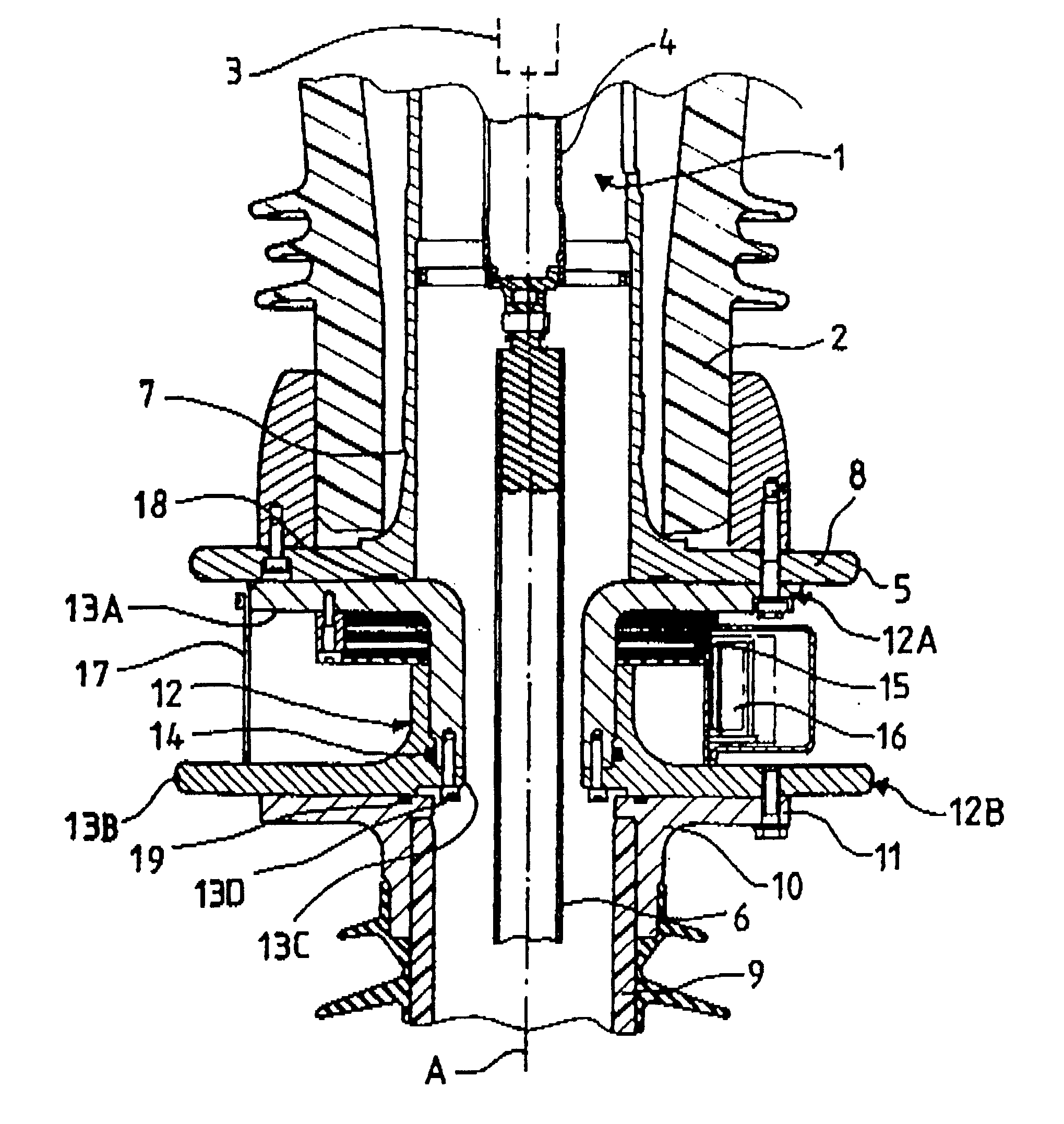
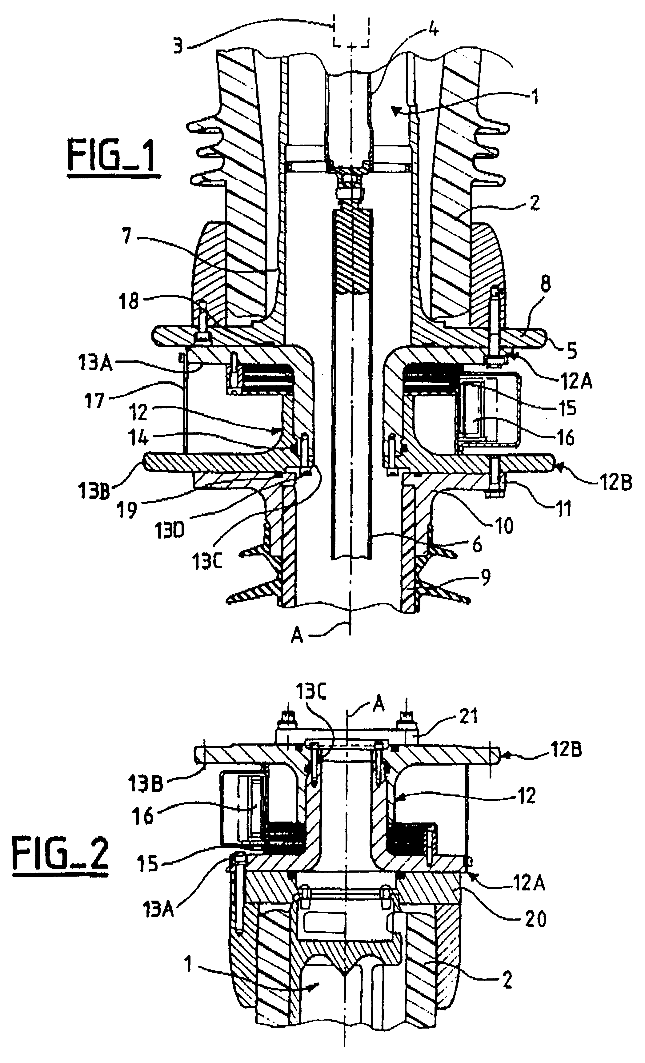
The circuit-breaker, only a small part of which is shown in FIG. 1, is a column circuit-breaker that includes an interrupting chamber 1 formed by a tube 2 which is made of an electrically insulating material, e.g. a ceramic or a composite glass fiber and resin material, which, in this example, extends vertically along an axis A, and in which a first contact 3 and a second contact 4 are disposed. The tube 2 is filled with an insulation gas having high dielectric power, such as SF.sub.6, under a pressure of a few bars. The contact 3 is electrically connected to a first terminal (not shown) provided at the top end of the tube 2. The contact 4 is mounted in the tube 2 to move relative to the contact 3 along the axis A, and it is connected mechanically to the contact 4 so as to move it along said axis, thereby opening or closing the circuit between the two terminals of the circuit-breaker. The contact 4 is connected electrically to a metal strength member or tubular flange-coupling piece...


PUM


Abstract

The single-phase circuit-breaker comprises at least one interrupting chamber formed by an insulating tube filled with an insulation gas, and it comprises at least one current transformer whose secondary is disposed in air around the primary at one end of the tube. The primary is at the high voltage electrical potential of the phase and is constituted by an annular metal support. The secondary is subjected to a high voltage electrical potential that is practically equal to the potential of the primary. The current transformer is thus integrated in the circuit-breaker, and the measurement electronics associated with the secondary can be located in air close to the secondary.

Description

The invention relates to a single-phase high voltage circuit-breaker comprising at least one interrupting chamber formed by an insulating tube filled with an insulation gas, and having, for at least one interrupting chamber, a current transformer which comprises a primary and a secondary. The secondary is disposed in air around the primary at one end of the tube, and the primary is at the high voltage electrical potential of the phase.Patent document FR 2 525 807 discloses a high voltage circuit-breaker of that kind, in which the primary is constituted by a tubular conductor immersed in the insulation gas of the interrupting chamber. In an embodiment shown in FIG. 3 of that document, the secondary is based on a metal sleeve which surrounds the primary at one end of the insulating tube of the interrupting chamber. The sleeve is secured to a metal casing connected to ground potential and thus constitutes an electrostatic screen which enables the secondary to be at an electrical potent...

Claims


Application Information

Patent Timeline
Patent Type & Authority Patents(United States)
IPC IPC(8): H01H33/02
CPCH01H33/027
Inventor LUSCAN, BRUNOLIBAUD, ALAINGREJON, OLIVIER
Owner ALSTOM TECH LTD
Why Eureka
Try Eureka