Check patentability & draft patents in minutes with Patsnap Eureka AI!

Valve for dosing the admission of volatilized fuel

a technology of valves and fuel injection, which is applied in the direction of valves, operating means/releasing devices, machines/engines, etc., can solve the problems of long opening and closing time, difficult use of direct gasoline injection engines,

Inactive Publication Date: 2002-07-09
ROBERT BOSCH GMBH
View PDF3 Cites 33 Cited by
  • Summary
  • Abstract
  • Description
  • Claims
  • Application Information

AI Technical Summary

Problems solved by technology

Because of their structure, such valves are not suitable for large flow quantities, and in particular their use in direct gasoline injection engines is problematic.
Because of these size ratios, quite a long valve stroke is required for pumping a certain predetermined quantity, which results in long opening and closing times. Furthermore, such a long stroke creates not inconsiderable background noise when the valve opens and closes.

Method used


Image

  • Valve for dosing the admission of volatilized fuel
  • Valve for dosing the admission of volatilized fuel
  • Valve for dosing the admission of volatilized fuel

Examples


Embodiment Construction

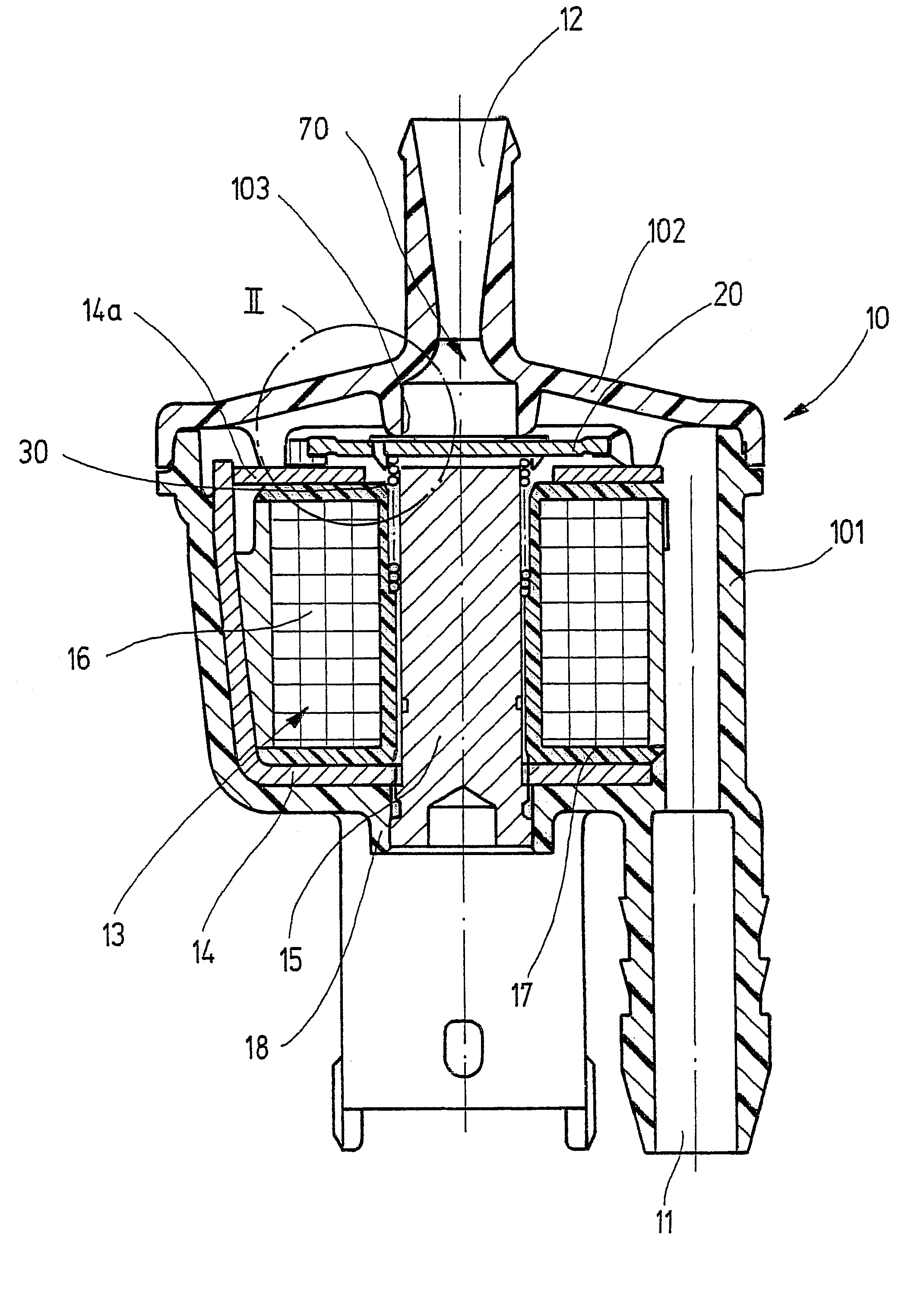
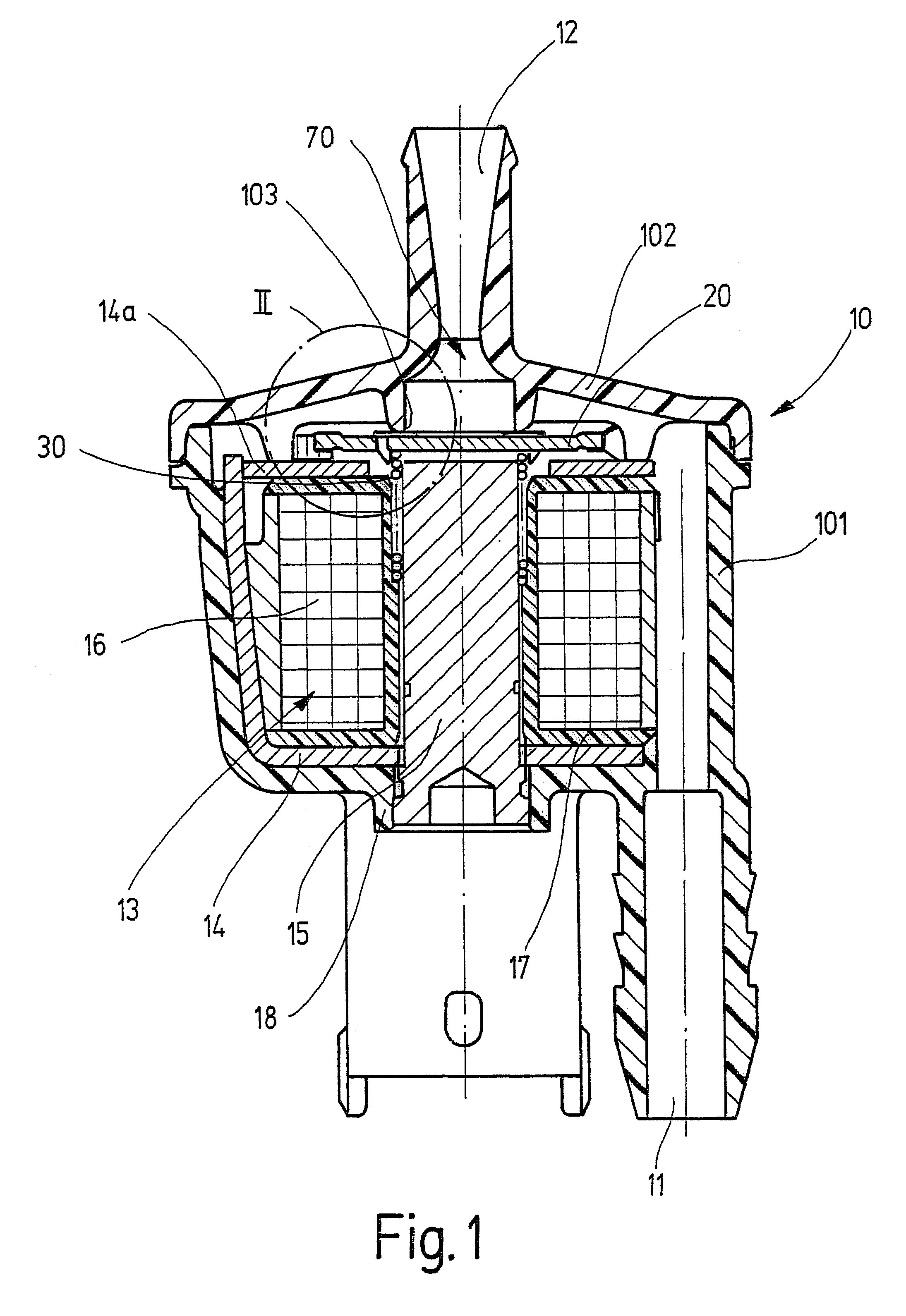
A tank venting valve, shown in longitudinal section in FIG. 1 as an exemplary embodiment of an arbitrary magnet valve, serves to provided metered admixture of fuel, volatilized from the fuel tank of a mixture-compressing internal combustion engine (not shown) with externally supplied ignition, into the engine, for instance into an intake tube, or in the case of direct gasoline injection, directly into a cylinder of the engine, and is part of a fuel vapor trapping system, not shown in further detail, of an internal combustion engine. The structure and function of such fuel vapor trapping systems can be learned for instance from "Bosch Technische Unterrichtung Motormanagement Motronic" [Bosch Technical Instruction Manual, Motronic Motor Management], 2nd Edition, August 1993, pp. 48 and 49. A tank venting valve and its function are disclosed for instance by German Patent Disclosures DE 40 23 044 A1 and DE 195 16 545 A1, which are hereby incorporated by reference.

The tank venting valve ...


PUM


Abstract

A magnet valve for tank venting in motor vehicles, having at least one valve opening forming a sealing seat and having a spring-loaded valve member cooperating with the at least one sealing seat for opening and closing the valve and actuated by an electromagnet counter to the restoring force of a restoring spring. Downstream of the valve member, a flow element that throttles the flow of a gas is disposed, the shape of the flow element is adapted to the opening cross section of the sealing seat that cooperates with the valve member, for determining (metering) the flow quantity of the gas through the cross section of the flow element when the magnet valve is open. The shape of the flow element is determined (metered) in such a way that the area of the opening cross section of the effective valve seat is greater than 2.5 and preferably greater than 9 times the area of the effective cross section of the flow element.

Description

PRIOR ARTThe invention relates to a valve for the metered introduction of fuel into engine in which the fuel is, volatilized from a fuel tank of an internal combustion engine.Such valves are known for instance from German Patent Disclosures DE 40 23 044 A1 and DE 195 16 545 A1; they serve to regenerate adsorption filters for fuel vapor trapping systems for vehicle fuel tanks. These magnet valves have a hollow-cylindrical magnet core, which is joined to a valve seat body that forms the short-circuit yoke of the electromagnet, covers the magnet housing, and rests peripherally on an annular rib. Annular slits which form an opening cross section of defined size are disposed in the valve seat body.Because of this structural design, a predeterminable volume of fuel vapors can be aspirated away, for a predetermined stroke of the valve member. This volume is defined by the maximum possible opening cross section of the hollow-cylindrical magnet core and of the opening slits in the valve seat...

Claims


Application Information

Patent Timeline
IPC IPC(8): F02M25/08F16K31/06
CPCF02M25/0836F16K31/0658F02M2025/0845Y10T137/8122
Inventor KRIMMER, ERWINSCHULZ, WOLFGANGMIEHLE, TILMAN
Owner ROBERT BOSCH GMBH
Features
  • R&D
  • Intellectual Property
  • Life Sciences
  • Materials
  • Tech Scout
  • Unparalleled Data Quality
  • Higher Quality Content
  • 60% Fewer Hallucinations
Learn More