Brass insert molded into "church window" of service accelerated release valve gasket

a technology of gasket and insert, which is applied in the direction of braking system, braking components, transportation and packaging, etc., can solve the problems of gasket distortion in the service portion of the brake control valve, the effect of avoiding the appearance of minor defects

Inactive Publication Date: 2002-07-09
WESTINGHOUSE AIR BRAKE TECH CORP
View PDF6 Cites 2 Cited by
  • Summary
  • Abstract
  • Description
  • Claims
  • Application Information

AI Technical Summary

Benefits of technology

It is, therefore, one of the primary objects of the present invention to provide a gasket which will resist leakage under high pressure differential conditions.

Problems solved by technology

Some of the improvements may have seemed minor, however, any improvement that can make a braking system more reliable and, thus, safer is never looked upon as minor.
Some problems have sporadically been encountered during periods under high pressure differential conditions.
When a high pressure differential condition exists between ER and BP, with ER being the higher pressure, distortion of a gasket can occur in the service portion of a brake control valve.
Depending on the magnitude of the distortion, the gasket's ability to seal can be affected which can, therefore, affect emergency braking.

Method used


Image

  • Brass insert molded into "church window" of service accelerated release valve gasket
  • Brass insert molded into "church window" of service accelerated release valve gasket
  • Brass insert molded into "church window" of service accelerated release valve gasket

Examples


Embodiment Construction

Prior to proceeding to the more detailed description of the present invention, it should be noted that for the sake of clarity in understanding the invention, identical components with identical functions have been designated with identical reference numerals throughout the drawing Figures.

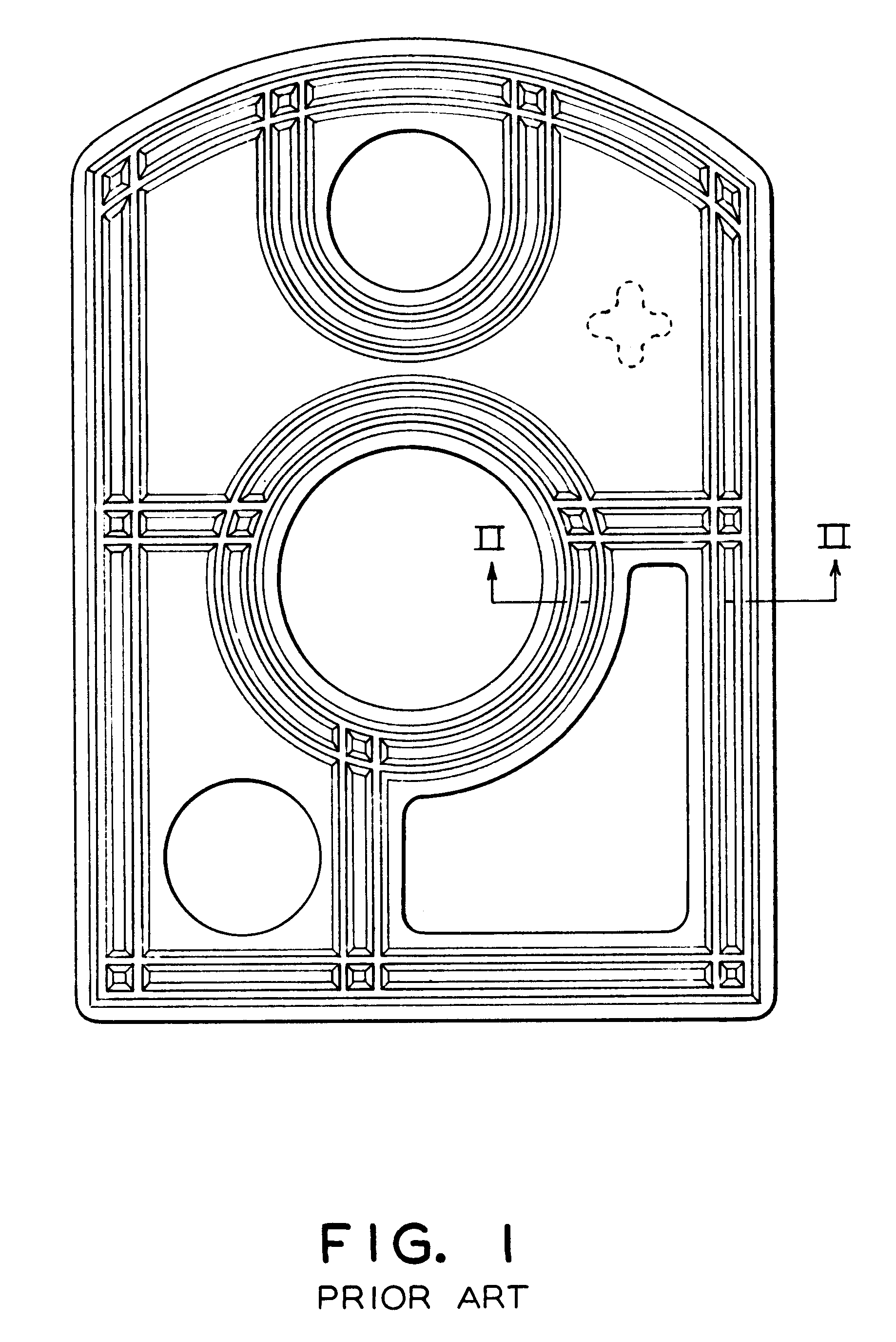
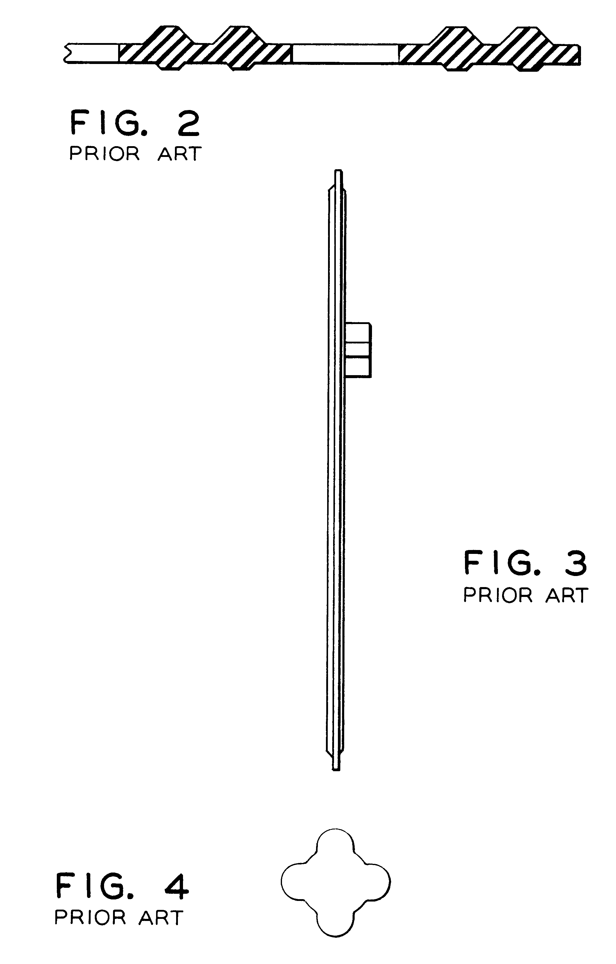
Before referring to the drawing Figures it should be noted that the basic shape and many of the features of the prior art gasket are still present in the gasket of the present invention; however, the present invention solves one of the critical problems that has been encountered in this portion of the braking system.

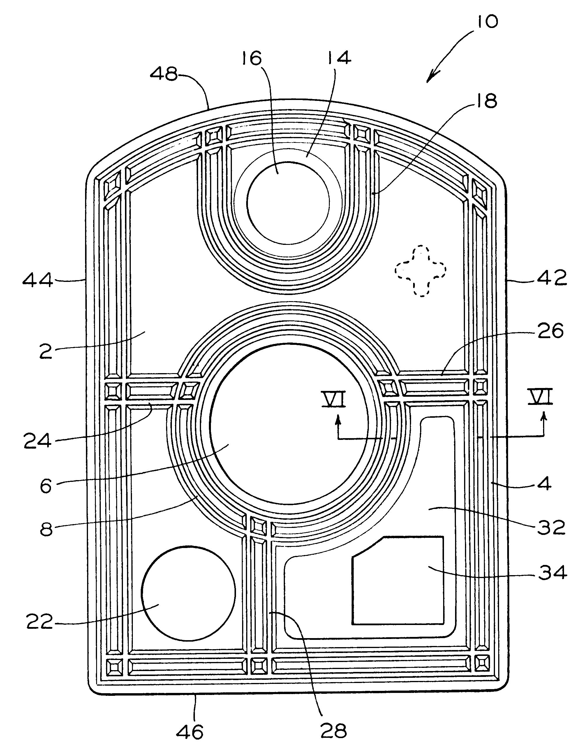
Reference is now made to FIGS. 5 thru 7. Illustrated therein is a gasket, according to the present invention, for maintaining the gasket in its proper position and for sealing the gasket between the body portion and the filling piece of the service portion of a brake control valve of a railway braking system.

The present invention provides a gasket, generally designated 10, for use in a...


PUM


Abstract

The present invention provides a gasket for use in a service portion of a brake control valve in a railway braking system. The gasket comprises an elastomeric composition with a predetermined shape. There is a series of bead-like projections formed on the first surface of the gasket for sealing such gasket with a body portion of the valve. A first aperture is disposed in the gasket at a predetermined location for engagement with a projection on the filling piece of the service portion. A brass insert is molded into the elastomeric composition and has a second aperture formed therein. The second aperture is in fluid communication with an auxiliary reservoir of such railway braking system. A third aperture is formed in the gasket in a third predetermined location. A brass insert, which has a first predetermined configuration, is molded into the elastomeric composition of the gasket. The brass insert is disposed in a lower quadrant of the first surface of the gasket and has a fourth aperture disposed therein having a second predetermined configuration. The fourth aperture is in fluid communication with a brake pipe. There are bead like projections formed on the opposed planar second surface of the gasket that correspond to similar positions, but radially opposed, for each of the bead like projections formed on the first surface of the gasket. The bead like projections formed on second surface are for sealing contact with such filling piece of such service portion.

Description

The present invention relates, in general, to railway braking systems and, more particularly, the present invention relates to a modification in the service accelerated release valve gasket to help eliminate emergency reservoir (ER) to brake pipe (BP) gasket leakage.Braking systems on railway vehicles, or with any type of moving vehicle, is an extremely important component. Any problems that occur in a braking system are deemed to be serious and attempts to eliminate or improve any such problems are given the highest priority.Since the introduction of pneumatic braking systems more than 125 years ago, such railway braking systems have been constantly modified and revised to improve braking performance. Some of the improvements may have seemed minor, however, any improvement that can make a braking system more reliable and, thus, safer is never looked upon as minor.New freight brake control valves, empty / load equipment, single sided brake pipe brackets, along with single car testing ...

Claims


Application Information

Patent Timeline
Patent Type & Authority Patents(United States)
IPC IPC(8): B60T15/00B60T15/48F16J15/12B60T15/02F16J15/06
CPCB60T15/48F16J15/122
Inventor SKWERES, JEFFREY B.TROIANI, VINCENT F.JOHNSTON, GREGORY L.
Owner WESTINGHOUSE AIR BRAKE TECH CORP
Why Eureka
Try Eureka