Evacuated package and a method of producing the same

a technology of vacuum sealing and packaging, applied in the direction of liquid dispensing, container/bottle contruction, rigid containers, etc., can solve the problems of rough hole 5, concave portions and convex portions, and the inability to reliably vacuum seal the vacuum element 4

Inactive Publication Date: 2002-07-09
COMPAQ COMP CORP +1
View PDF12 Cites 57 Cited by
  • Summary
  • Abstract
  • Description
  • Claims
  • Application Information

AI Technical Summary

Problems solved by technology

However, according to the above structure in which the connecting hole 5 is closed with the sealing film 6, a disadvantage is that the vibrating element 4 cannot be reliably vacuum-sealed, a fact which is attributed to the following: Since the connecting hole 5 is made in the lid portion 2 by a piercing technique such as ultrasonic processing or sandblast processing, the inner face of the resulting connecting hole 5 is rough, or in other words, has concave portions and convex portions.
Thus, it is difficult to perfectly form the sealing film 6 on the inner face of the connecting hole 5 by sputtering, electron-beam deposition, or the like.
Thus, the space 3 is not perfectly sealed by the sealing film 6 and the air-tightness of the space 3 deteriorates, thereby decreasing the reliability of the vacuum-sealing of the vibrating element 4.

Method used


Image

  • Evacuated package and a method of producing the same
  • Evacuated package and a method of producing the same
  • Evacuated package and a method of producing the same

Examples


Embodiment Construction

The present invention will be better understood from the following description taken in conjunction with the accompanying drawings.

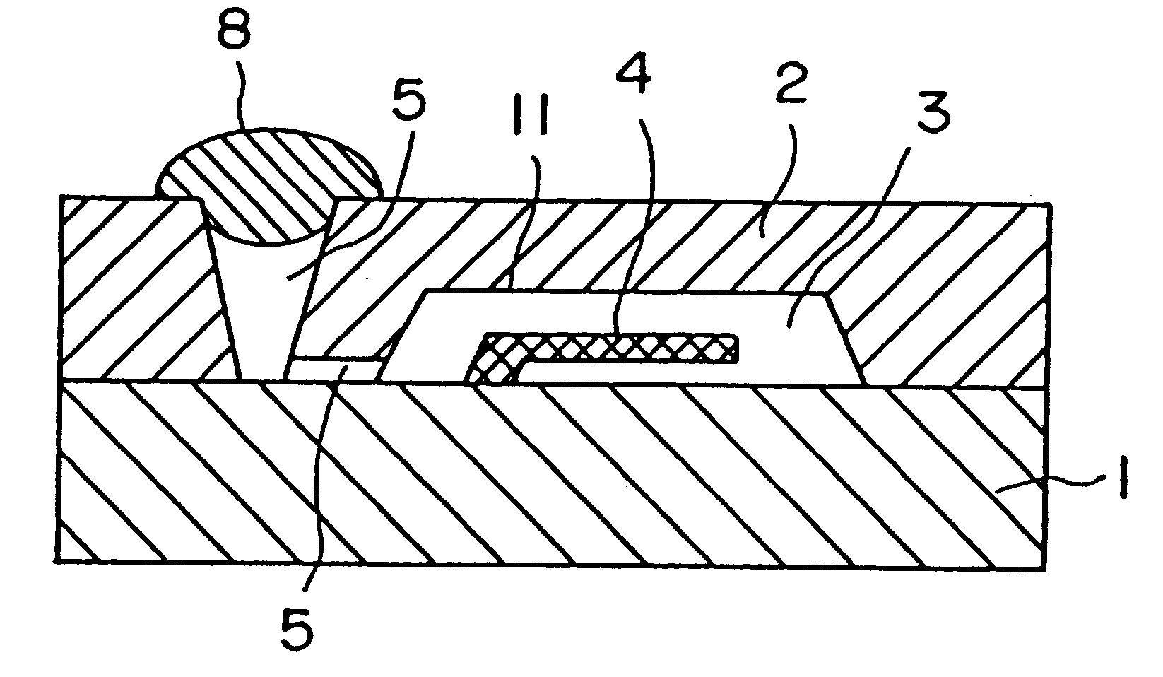
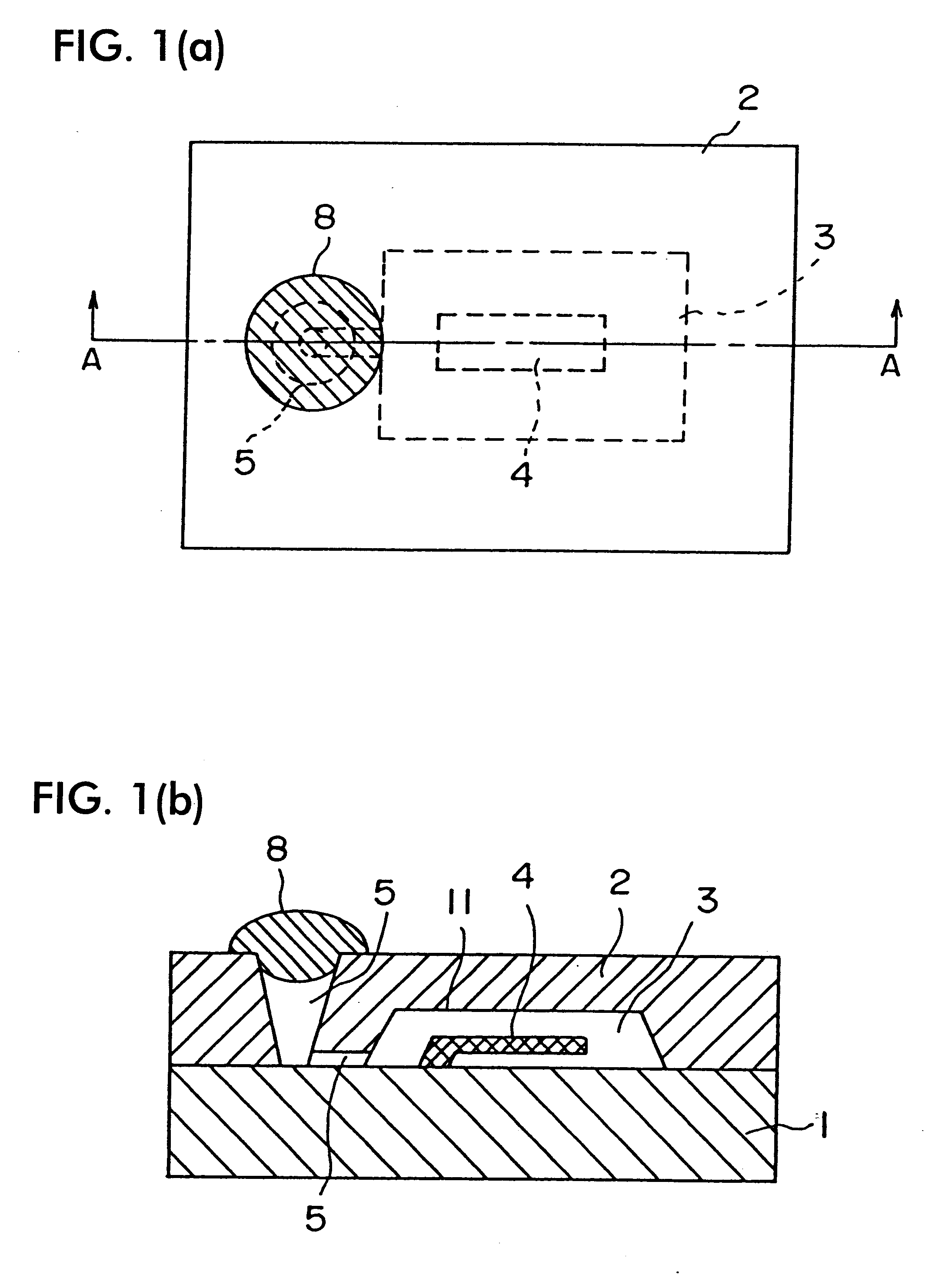
FIG. 1(a) shows a vacuum-sealed element which is obtained by packaging a vibrating element in a package structure according to an embodiment of the present invention, and FIG. 1(b) is a cross-sectional view taken along the line A--A in FIG. 1(a). The numerals in the different views identify substantially identical parts in the above conventional example, and detailed explanations thereof are omitted.

The evacuated package of this embodiment is composed of: a first substrate 1 made of silicon; a lid portion 2; a vibrating element 4 such as a micromechanical vibratory gyroscope; and a thermo-melting material 8 (i.e., material that melts due to heat) such as solder. As is shown in FIGS. 1(a) and 1(b), the vibrating element 4 is formed on the first substrate 1 by a semiconductor-device fabrication technique and the lid portion 2 is anode-coupled with the firs...


PUM

PropertyMeasurementUnit
volumeaaaaaaaaaa
thermo-meltingaaaaaaaaaa
semiconductoraaaaaaaaaa

Abstract

An evacuated package with highly reliable vacuum-sealing and a method for producing an evacuated package with the evacuatable package. A lid portion is joined onto a substrate with an element accommodated in an evacuated space formed by the substrate and the lid portion. A connecting hole in the lid portion extends from the space to the top face of the lid portion. A metal film is formed around the complete peripheral region of the opening of the connecting hole, and a thermo-melting material is joined to the metal film to close the opening of the connecting hole so as to seal the element in the evacuated space. Before closing the opening of the connecting hole with the thermo-melting material, the space is evacuated, and simultaneously, the thermo-melting material is melted by heat and left until completely degassed in a vacuum. The degassed thermo-melting material is then pressed and joined to the metal film around the periphery of the opening of the connecting hole to close the opening with the thermo-melting material and vacuum-seal the space.

Description

1. Field of the InventionThe present invention relates to an evacuatable package for sealing an element, such as a micromechanical vibratory gyroscope, in an evacuated space, to an evacuated package containing such an element, and to a method for producing such an evacuated package.More particularly, the present invention relates to an evacuated package comprising a substrate, a lid portion joined onto said substrate, an evacuated space formed by said substrate and said lid portion, an element formed on said substrate and contained in said evacuated space, and a connecting hole connecting said evacuated space with an opening formed on the top face of said lid portion.2. Description of the Related ArtFIG. 5 shows an example of a package structure for sealing a vibrating element, such as a micromechanical vibratory gyroscope, in an evacuated space. This evacuated package is composed of: a substrate 1 made of silicon, for example; a lid portion 2 to be anode-coupled with the substrate ...

Claims


Application Information

Patent Timeline
Patent Type & Authority Patents(United States)
IPC IPC(8): B81B7/00G01L9/00G01P1/02G01P5/00G01P1/00H01L23/10H01L23/02H03H9/10
CPCB81B7/0077G01L9/0019G01L9/0042G01P1/023H01L23/10G01P5/00B81C2203/0145Y10T428/1317H01L2924/01079H01L2924/0002H01L2924/00G01P2015/0828
Inventor HARA, TETSUZONEGORO, YASUHIRO
Owner COMPAQ COMP CORP
Why Eureka
Try Eureka