Signal coupler using low voltage filtering
a low-voltage filtering and signal coupler technology, applied in the field of signal couplers, can solve the problem that stages utilize a great deal of circuit board spa
Inactive Publication Date: 2002-07-09
EPIGRAM +1
View PDF11 Cites 20 Cited by
- Summary
- Abstract
- Description
- Claims
- Application Information
AI Technical Summary
Problems solved by technology
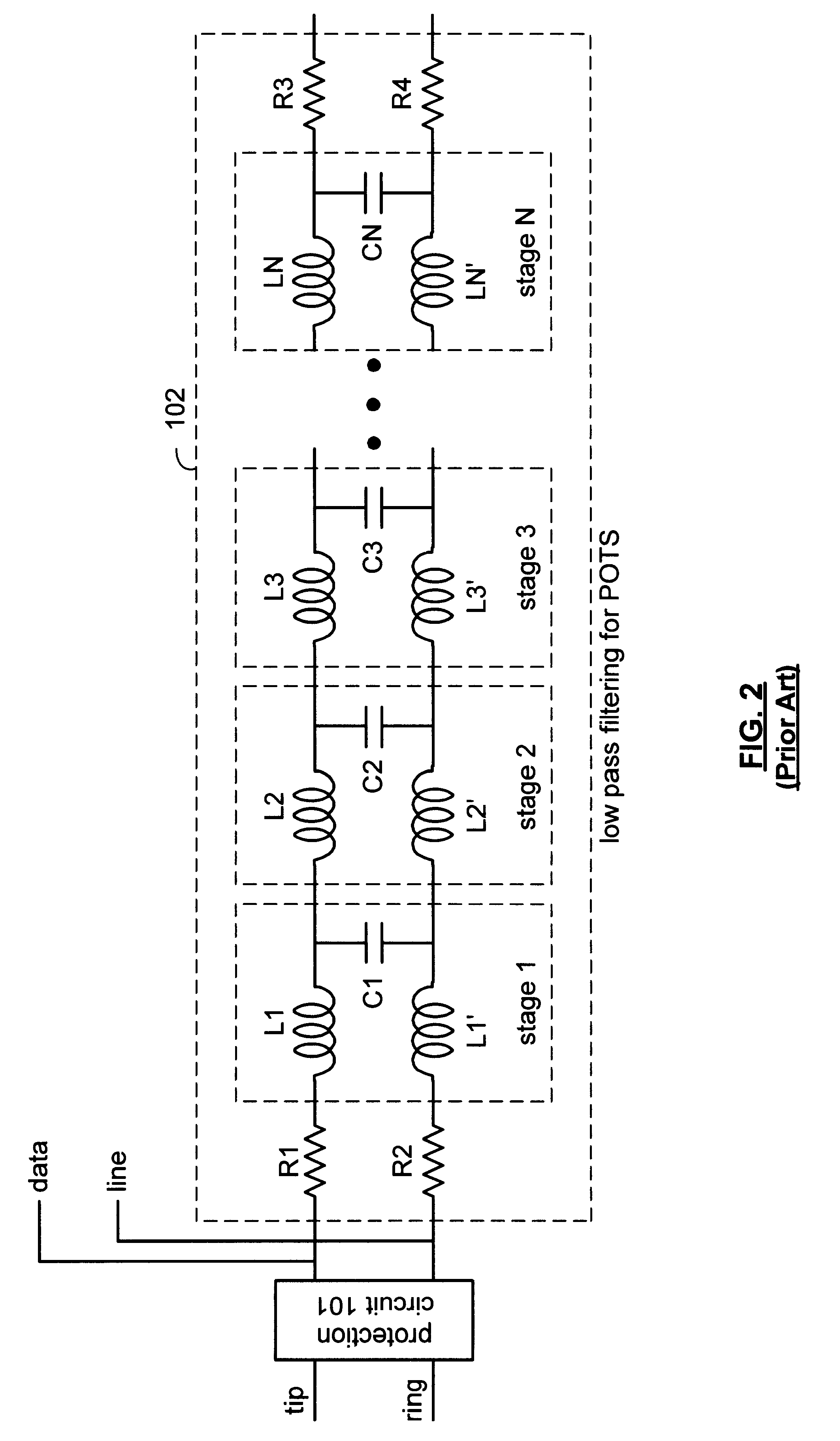
This necessitates that each of the components in the filtering circuit be discrete components which require a large amount of space on the circuit board.
More stages of filtering could be used at this point but, because of the high battery voltage, these stages utilize a great deal of circuit board space.
Method used
View moreImage
Smart ImageViewing Examples

Examples
second embodiment
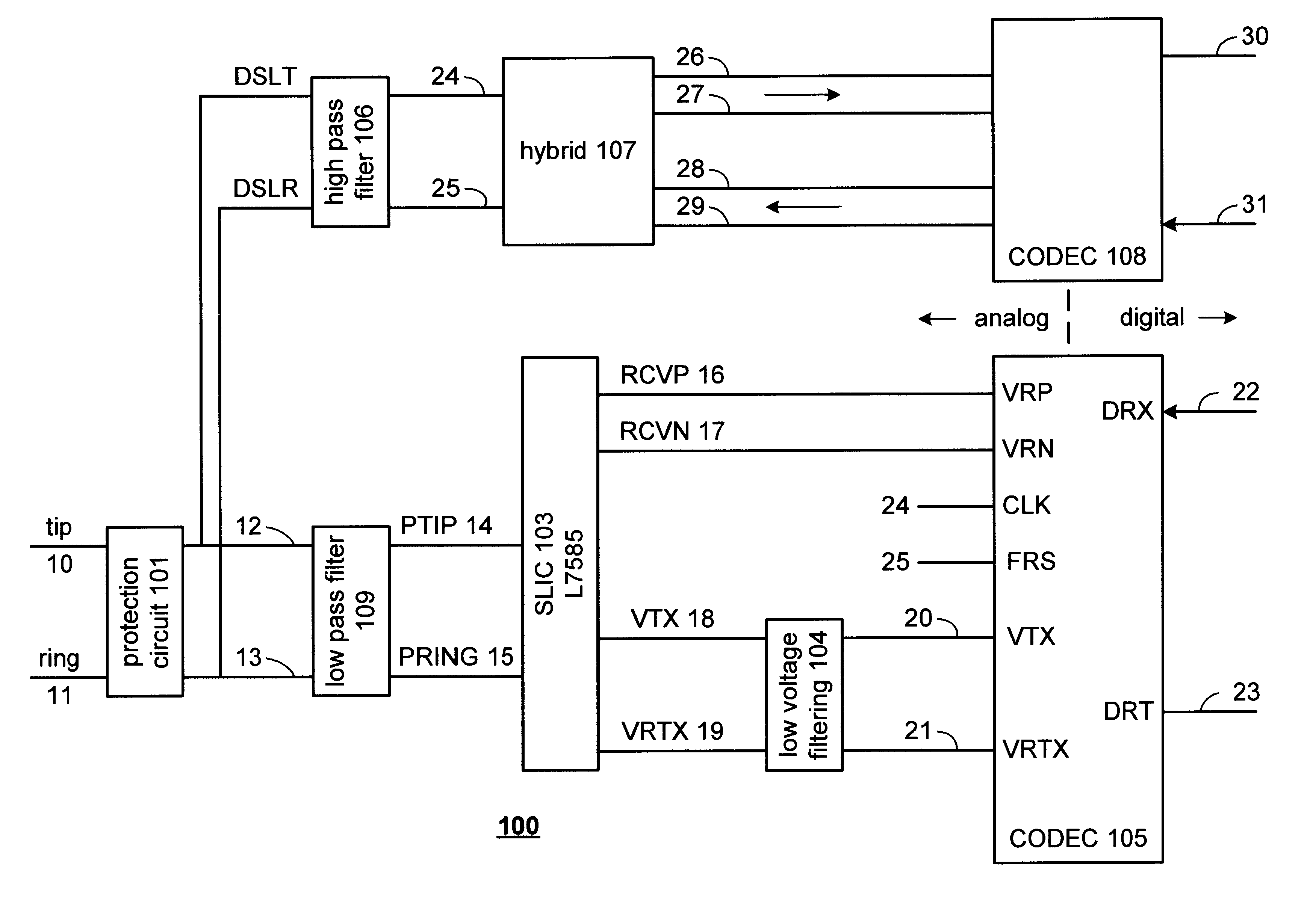
the invention is shown in FIG. 5. The embodiment shown in FIG. 5 differs from the preferred embodiment shown in FIG. 4 in that part of the filtering is shifted to the digital side of CODEC 105. In this embodiment, the filtering is split between a Low Voltage Filter 110 and a Digital Filtering Circuit 111 located on line 23.
The examples illustrated here are representative examples and in no way limit the scope of this application. Other obvious embodiments of the invention will be apparent to one skilled in the art and are included within the scope of this application. One obvious embodiment is to not have a data path so that only POTS signals are processed.
Login to View More PUM
 Abstract
A signal coupler is provided which decreases the number of discreet elements required to provide low pass filtering for the plain old telephone service (POTS). The low pass filtering is shifted to areas of the signal coupler circuit which do not operate with the high battery voltage present on telephone lines The low voltage filtering reduces the need for components which are capable of operating in the high voltage environment and therefore reduces the space on the circuit board which is occupied by each of the signal couplers. In this way, the number of individual subscriber lines that a given circuit board can accommodate can be increased.
Description
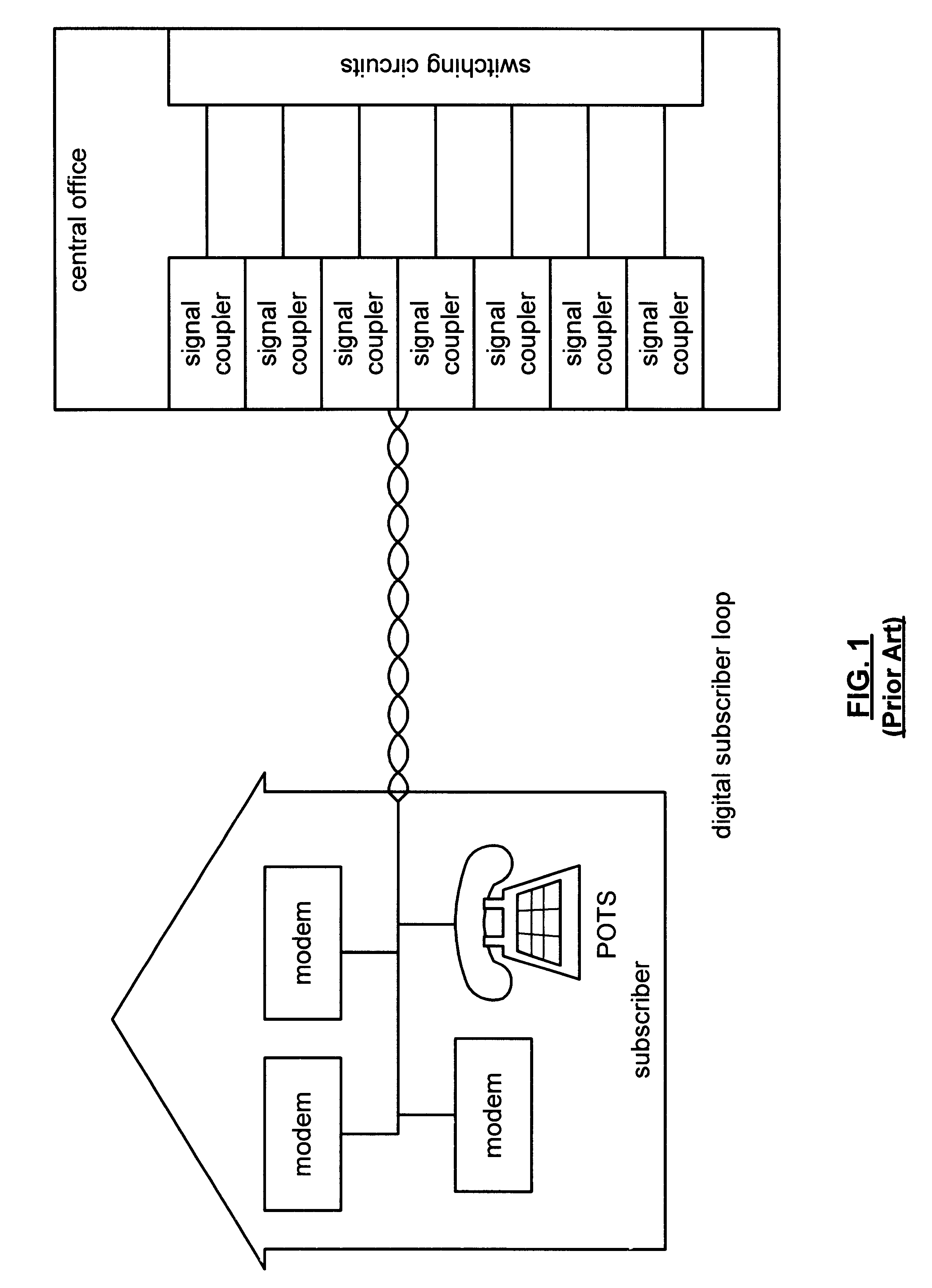
1. Field of the InventionThe invention relates to a signal coupler for telephone lines containing both plain old telephone service (POTS) and digital signals where low voltage filtering is used in the POTS channel.2. Description of the Related ArtModern data networks commonly use complex digital signal processing (DSP) devices called modems to transport data over communication channels. Data is typically transported via an analog transmission signal which is representative of a synchronous, constant rate bit stream. This form of communication channel is suitable for the transmission of real-time information such as voice or video.Often it is desirable to transmit both Plain Old Telephone Service (POTS) and digital data, either by Asymmetric Digital Subscriber Line (ADSL) or some other method, over the same line. The POTS frequency spectrum ranges from 300 to 3400 Hz. The ADSL frequency spectrum ranges from 24 kHz to 1100 kHz.As shown in FIG. 1, the data and POTS signals are transmit...
Claims
Login to View More Application Information
Patent Timeline
 IPC IPC(8): H04L27/00H04M3/00
CPCH04L27/0002H04M3/005H04M3/007
Inventor SNOW, DANE RODERICKROSEN, MARK
Owner EPIGRAM