Tobacco pipe

Inactive Publication Date: 2002-07-16
SANDIA
View PDF26 Cites 25 Cited by
  • Summary
  • Abstract
  • Description
  • Claims
  • Application Information

AI Technical Summary

Benefits of technology

Briefly, more fully and completely described hereinafter, the invention is incorporated into a tobacco pipe having a weighted turret rotatably mounted on a manifold, a stem for smoking attached to the manifold, a single chamber in the manifold, the turret having a plurality of magazines each capable of being aligned with the manifold's chamber by rotation of turret to manifold, a screen set within a recess of a port in the manifold--at a spacing distinctly distanced from the magazines to prevent scorching, a single joining member that provides one or more bearings to prevent binding between the turret and manifold, as well as fastening them together, all of which contributing to a unique smoking system. The turret is made of material heavier than that of the manifold, such as brass, while the manifold is made of aluminum. As metal is heated, it oxidizes, so brass is used for the turret to remove metal taste from the tobacco smoke being inhaled. The stem has a substantial thicker dimension, that may include additional surface areas over straight cylindrical wall areas of an ordinary metal pipe, to dissipate heat to a greater extent without the pipe getting hotter like other metal pipes in addition to providing a better grip on the pipe by its user. The magazines or chambers in the turret are of a cylindrical dimension, with a squared or 90-degree angled shelf that prevents substantially all of the ash residue from settling upon the lower disposed screen. The life of the single screen considerably spaced from the magazines thus is increased, while being functional for all magazines in the turret rather than making a screen for each magazine.
Another object of the invention is to provide a metal tobacco pipe that does not get hot to an extent that would be uncomfortable or injurious to the smoker holding it while inhaling its smoke.
A further object of the invention is to provide a metal tobacco pipe that eliminates a metal taste from the inhaled smoke.
A still further object of the invention is to prevent clogging in the smoking passages of the metal tobacco pipe.
Yet another object of the invention is to provide an increased period of time between the cleaning of a metal tobacco pipe.
A still further object of the invention is to provide a tobacco pipe more easily assembled and disassembled, for cleaning, repairing, and the like.

Problems solved by technology

Disadvantages in today's metal tobacco pipes is the metal taste in the inhalation of tobacco, the lack of sufficient dissipation of heat from the metal of the pipe, and the clogging of tobacco in passages between the tobacco-burning chamber and the pipe's stem.

Method used


Image

  • Tobacco pipe
  • Tobacco pipe
  • Tobacco pipe

Examples


Embodiment Construction

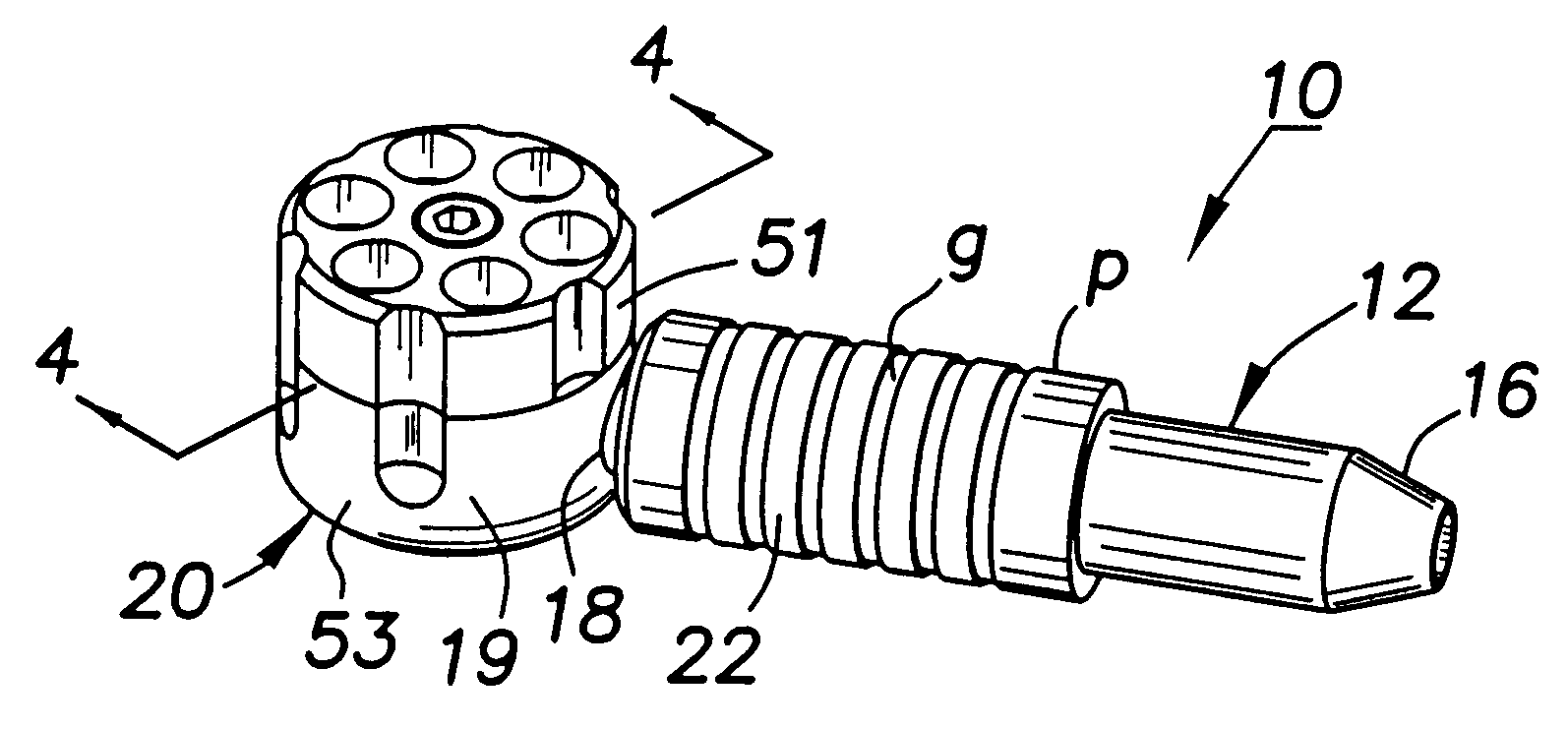
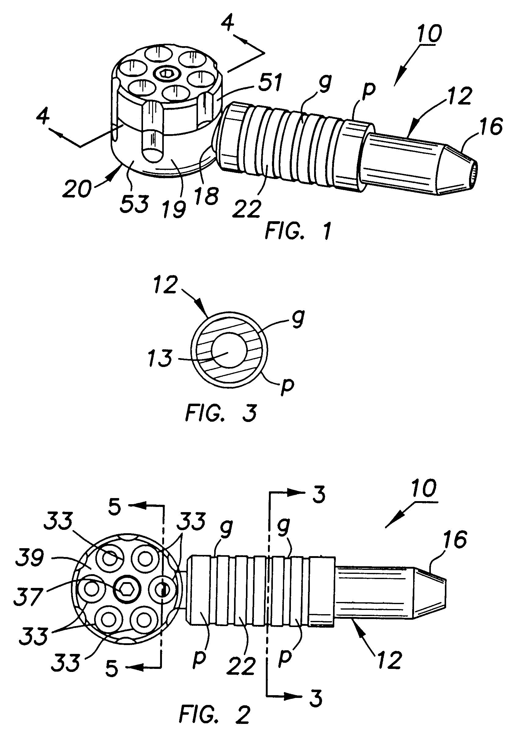
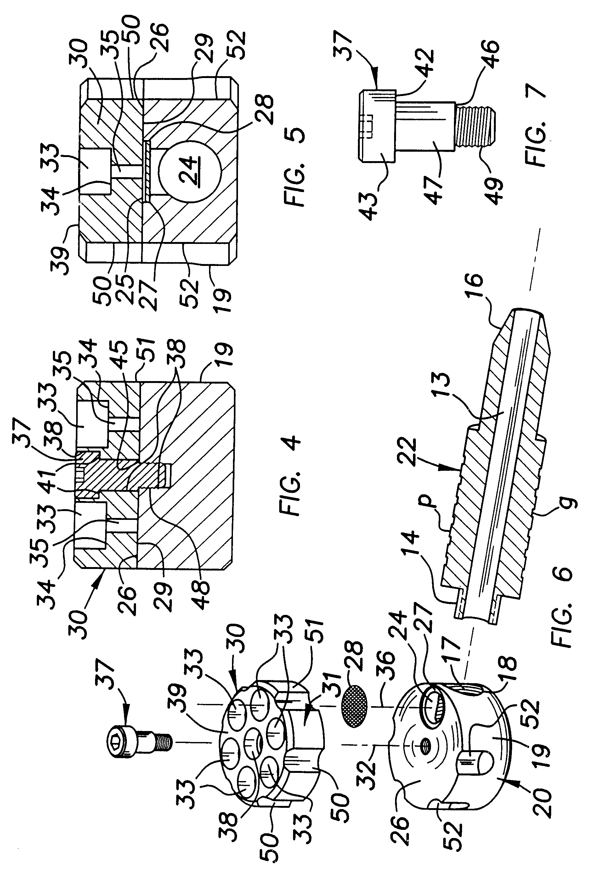
Referring now to the FIGURES accompanying this description and in which reference characters therein correspond to the numerals hereinafter, FIGS. 1-6 illustrate the preferred embodiment of the invention. The tobacco pipe 10, FIG. 1, comprises a stem 12 having a bore 13, FIG. 6, through which smoke is inhaled in use of the pipe, including a threaded end portion 14, FIG. 6, opposite its mouth-portion end 16. Portion 14 is threaded to corresponding threads 17 forming an opening 18 through the wall or periphery 19, FIG. 6, of a cylindrical manifold 20 in the assembly of the illustrated five (5) 10 tobacco pipe, FIG. 1 11 12 stem 13 bore, FIG. 6 14 threaded end portion, FIG. 6 15 16 mouth-end portion 17 threads in 18, FIG. 6 18 opening in 19, FIGS. 1, 6 19 periphery / wall in 20, FIGS. 1, 6 20 cylindrical manifold 21 22 main body of 12 p periphery on 22 g grooves in 22 23 24 chamber in 30, FIGS. 5, 6 25 port, FIG. 5 26 top wall of 20, FIGS. 5, 6 27 recess in 25 28 screen 29 bottom wall of...


PUM


Abstract

A tobacco pipe (10) having a hollow stem (12) threaded to a manifold (20) on top of which a turret (30) is rotatably mounted. Turret (30) is of greater weight than that of manifold (20), so that any one of a plurality of turret magazines (33) remains stationary over a chamber (24) in the manifold (20) in their relative rotation, so that smoking tobacco in the aligned magazine (33) with such chamber (24) takes place through the hollow stem (12). A screen (28) seats in a recess 27 of a port (25) of manifold (20) at a sufficient distance from the turret's chamber (24), preventing scorching of screen (28) by a source of flame at / in chamber (24) in the aligned magazine (33). A member (37) is seated in a cavity (38) co-extensive between and within turret (30) and manifold (20), and includes a bearing surface (42) that abuts a bearing surface (41) in turret (30) and includes threads (48) disposed within manifold (20) and threads (49) in turret (30) for fastening turret (30) to manifold (20) in an unbinding manner due to the assembly of abutting bearing surfaces (42, 41). A second set of bearing surfaces (46, 45) are provided in member (37) and manifold (20), respectively. Series of fluted surfaces (50, 52) on peripheries (51, 19) of turret (30) and manifold (20) assists in aligning a magazine (33) with chamber (24). Weight of turret (30) over that of manifold (20) maintains a stationary position between the two during a smoking mode. Pipe (10) is free of clogging and residue that otherwise would adhere to screen (28) due to a wide shelf (34) for the magazines (33).

Description

TECHNICAL FIELDThis invention is directed to a tobacco pipe and in particular is directed to an improvement in a magazine-type pipe by which more than one magazine or chamber for tobacco is available and from any one of which the smoke of the tobacco can be inhaled.BACKGROUND TO THE INVENTIONa) Prior Art TeachingsThe U.S. patents to Hurst [U.S. Pat. No. 1,302,047, granted Apr. 29, 1919] and Locke [U.S. Pat. No. 4,171,703, granted Oct. 23, 1979] disclose tobacco pipes that include within their bowls a plurality of magazines or chambers for containing tobacco, with any one of the magazines being serially communicable with smoke passages through which the smoke of the burning tobacco can be inhaled. In Hurst, each magazine communicates with a smoke passage in a base and which in turn communicates with a smoke passage in a hollow stem through which smoke is inhaled. A pivot pin rotatably secures the bowl and base together, and further requiring spring and packing members to assure smoke...

Claims


Application Information

Patent Timeline
IPC IPC(8): A24F5/00
CPCA24F5/00
Inventor LEE, JAKE
Owner SANDIA
Why Eureka
Try Eureka