Parallel contact circuit breaker

a circuit breaker and contact technology, applied in circuit breaker switches, protective switch details, switches with electromagnetic release, etc., can solve the problems of large load-handling capacity devices that are typically dimensionally larger, possible failure, and the contact resistance of a switch may change significantly

Inactive Publication Date: 2002-07-16
SENSATA TECH MASSACHUSETTS INC
View PDF37 Cites 23 Cited by
  • Summary
  • Abstract
  • Description
  • Claims
  • Application Information

AI Technical Summary

Benefits of technology

The applicants have found that a single magnetohydraulic trip element can advantageously be used to provide desired trip dynamics in a circuit breaker by passing all current from a set of parallel contact sets through a unitary trip element, and providing a multipole trip arm triggered by the unitary trip element which trips the parallel contact sets simultaneously.
The preferred design employs parallel circuit breaker poles each having a trip mechanism, switch contacts and a housing, which share most components in common with a single pole circuit breaker in the same "family", thus reducing required number of inventoried parts and engineering costs. The trip element of the preferred design, however, differs from single pole designs, being configured for the desired ratings and dynamic response, and portions of the housing between adjacent poles are modified for common access to electrical terminals to bridge the load and to provide a standard type multipole trip bar. The magnetohydraulic trip element, which is preferably a 150 Amp element with desired dynamic trip characteristics, sits asymmetrically in one of the pole housings within a standard frame, in the normal trip element position, and actuating a standard armature.
It is therefore an object of the invention to provide a magnetohydrodynamic circuit breaker which has a low average overcurrent trip capability with good nuisance trip immunity.

Problems solved by technology

These larger load-handling capacity devices are typically dimensionally larger than lower load carrying designs.
This is because a contact set having a lower impedance than others will "hog" the current, and may thus see a significantly greater proportion of the total current than 50%, resulting in overheating, and possible failure.
Further, the contact resistance of a switch may change significantly with each closure of the switch.
However, this does not compensate for unequal contact resistance, and nuisance tripping of the circuit breaker results when the unequal division of the current has caused enough current to pass through one of the current sensing devices to cause it to trip its associated mechanism.
For example, if the maximum expected deviation in contact resistance of the contact sets (which changes each time the contact is closed) could cause a current splitting ratio of 60% / 40%, then in order to ensure reliable trip at 135% of total rated capacity, each trip element must be designed to trip at about 120% of rated capacity, which would lead to unreliability and nuisance trips because of insufficient margin.
Notwithstanding the foregoing attempts, it has heretofore been considered difficult to employ magnetohydraulic circuit breakers in parallel contact multipole breakers with relatively low overcurrent thresholds, such as that imposed by UL 489, especially for use in load environments with high peak to average load ratios, because the maximum expected currents would result in nuisance trips.
The need to have a different set of component and case sizes for each current rating has added to the overall cost of breakers of this general type.
However, such thermal magnetic designs typically require calibration of the thermal trip mechanism for precision, and tuning of dynamic response is difficult.
Further, the thermal element incurs a wattage loss.
Nuisance tripping is a problem in applications where current surges are part of the normal operation of a load, such as during motor start-up or the like.
For example, starting up of motors, particularly single phase, AC induction types, may result in high current surges.
Surges of this type will cause nuisance tripping in conventional delay tube type electromagnetic circuit breakers.

Method used


Image

  • Parallel contact circuit breaker
  • Parallel contact circuit breaker
  • Parallel contact circuit breaker

Examples


Embodiment Construction

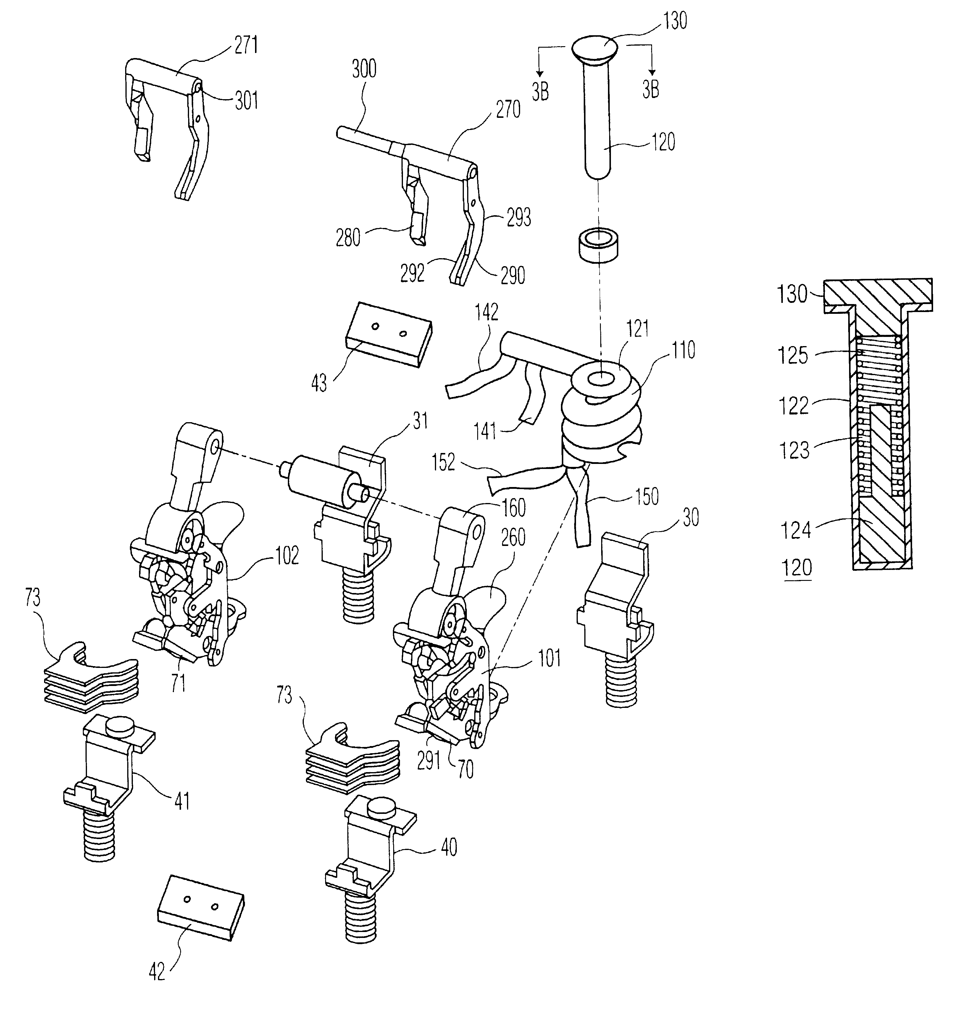
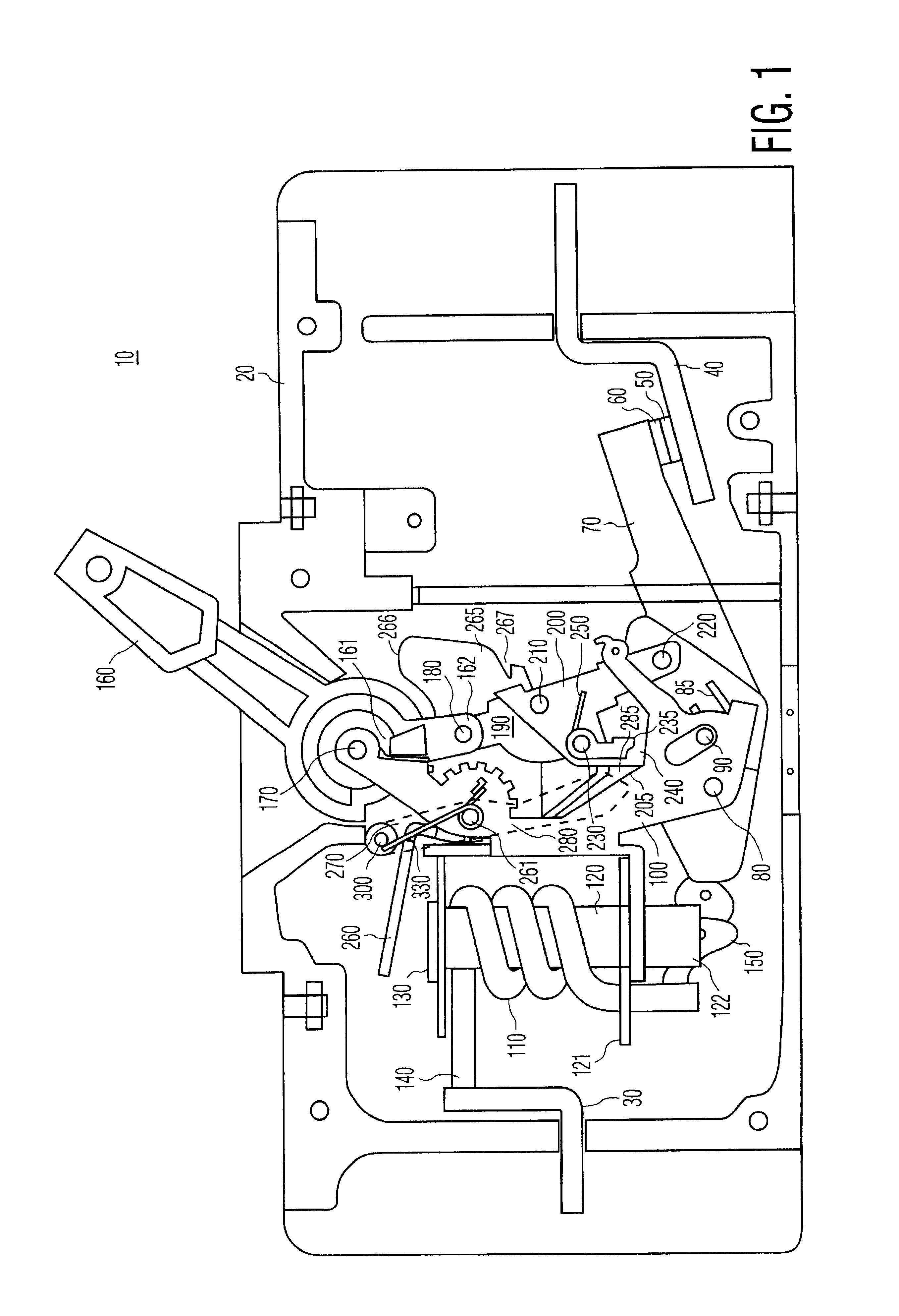
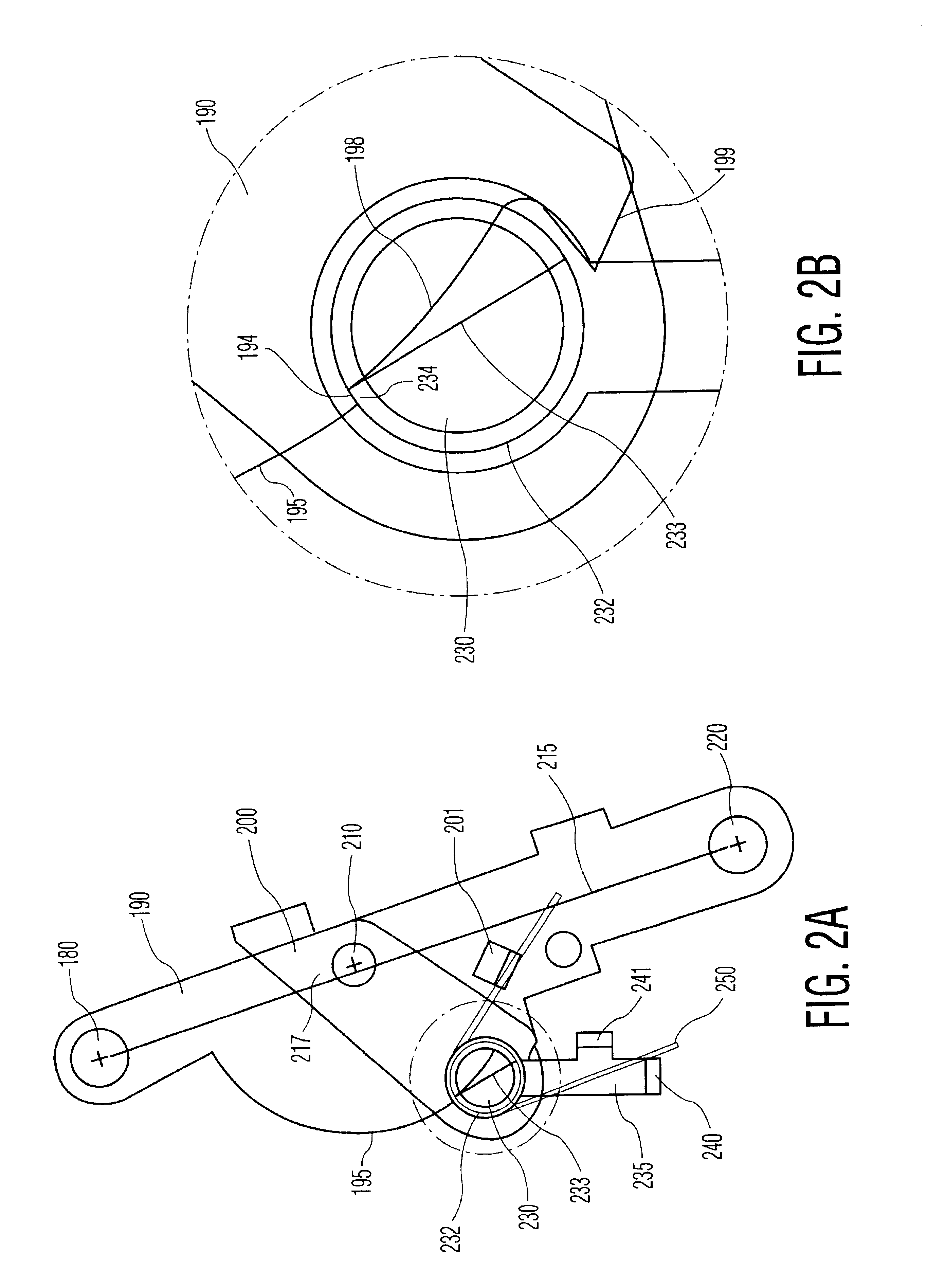
Components of a conventional type single pole circuit breaker are depicted in FIGS. 1, 2A and 2B. See, U.S. Pat. No. 5,293,016, expressly incorporated herein by reference. As shown, the single pole circuit breaker 10 includes an electrically insulating casing 20 which houses, among other things, stationary mounted terminals 30 and 40. In use, these terminals are electrically connected to the ends of the electrical circuit that is to be protected against overcurrents.

As its major internal components, a circuit breaker includes a fixed electrical contact, a movable electrical contact, an electrical arc chute, a slot motor, and an operating mechanism. The arc chute is used to divide a single electrical arc formed between separating electrical contacts upon a fault condition into a series of electrical arcs, increasing the total arc voltage and resulting in a limiting of the magnitude of the fault current. See, e.g., U.S. Pat. No. 5,463,199, expressly incorporated herein by reference. T...


PUM


Abstract

A parallel pole magnetohydraulic circuit breaker (10), having a single trip element (271) and a pair of trip mechanisms (101, 102), achieving an increased current carrying capacity with reduced nuisance trips. The tip mechanisms (101, 102) are contained within separate housings (14, 16), with electrical connections (30, 40) and multipole trip mechanism (101, 102) communicating through apertures in the common wall (14'). Preferably, the armature (260) of the trip element (271) acts on a single trip mechanism (101, 102), which multiplies the available force to trigger a trip of the other tip mechanism.

Description

The present invention relates to the field of circuit breakers, and more particularly to multipole circuit breakers in which contact sets are paralleled in order to increase breaker capacity rating.In the field of electrical circuit breakers, it is well known to tie the mechanisms of a plurality of electrical poles, or independent circuit paths, together. In this case, it is often desired to provide a single control lever and a trip mechanism which operates the electrical contacts in synchrony. See, U.S. Pat. Nos. 5,565,828; 5,557,082, 4,492,941, and 4,347,488, expressly incorporated herein by reference.A single pole circuit breaker is a device that serves to interrupt electrical current flow in an electrical circuit path, upon the occurrence of an overcurrent in the circuit path. On the other hand, a multipole circuit breaker is a device which includes two or more interconnected, single pole circuit breakers which serve to substantially simultaneously interrupt current flow in two ...

Claims


Application Information

Patent Timeline
Patent Type & Authority Patents(United States)
IPC IPC(8): H01H71/10H01H71/12H01H71/34H01H71/44H01H73/06H01H73/02
CPCH01H71/1027H01H71/1045H01H71/345H01H71/446
Inventor RUNYAN, DANIEL
Owner SENSATA TECH MASSACHUSETTS INC
Why Eureka
Try Eureka