
Method and system for preventing deposition on an optical component in a spectroscopic sensor

a technology of optical components and spectroscopic sensors, applied in the direction of optical radiation measurement, instruments, spectrometry/spectrophotometry/monochromators, etc., can solve the problems of reducing the reflectivity of affecting the sensitivity and operation of the sensor, and often impractical to place the light source and the detector very far apar

Inactive Publication Date: 2002-07-16
LAIR LIOUIDE POUR LETUD ET LEXPL DES PROCEDES GEORCLAUDE +1
View PDF10 Cites 62 Cited by
  • Summary
  • Abstract
  • Description
  • Claims
  • Application Information

AI Technical Summary

Problems solved by technology

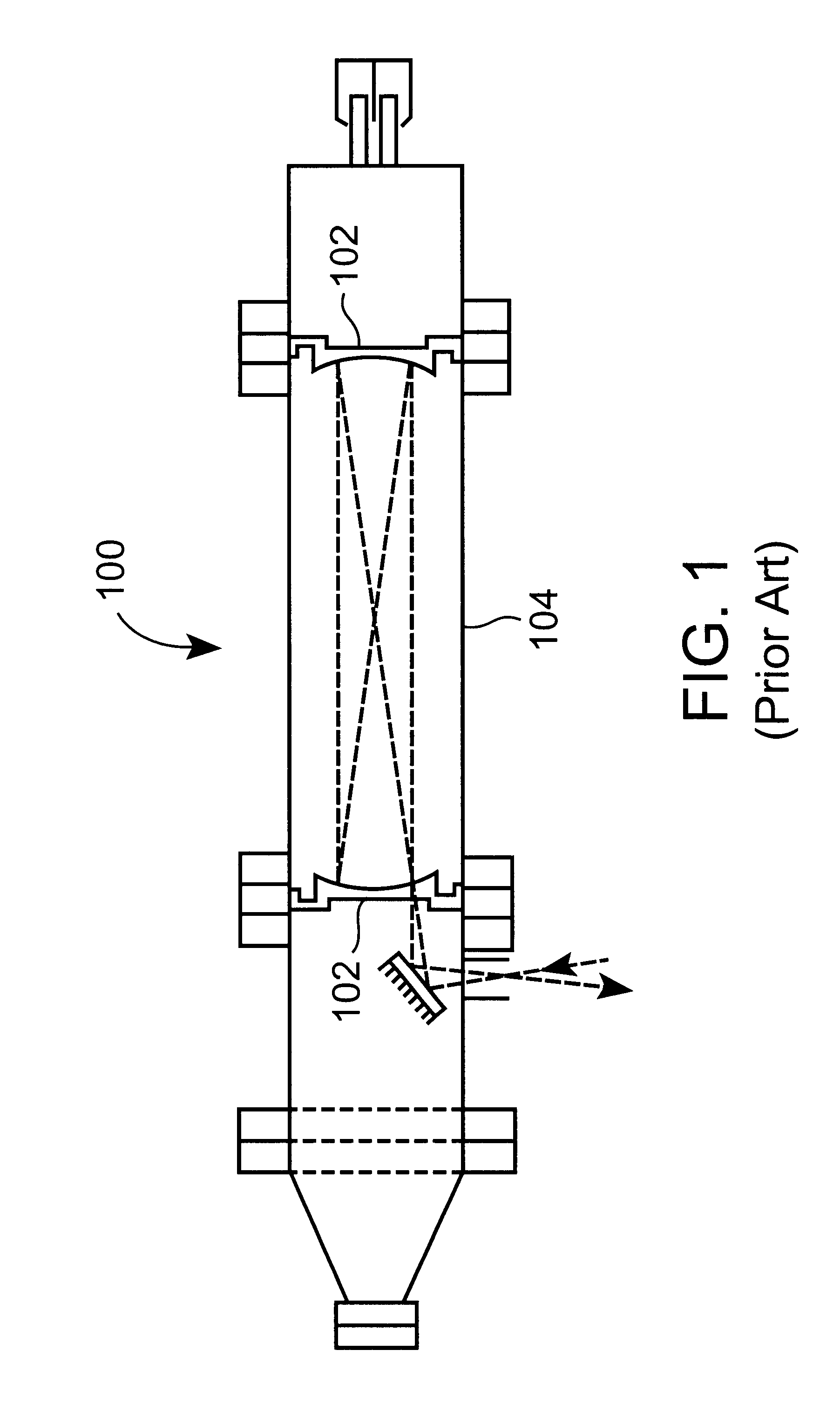
In order to make l large, it is frequently impractical to place the light source and detector very far apart.
Deposits formed on the optical components of a spectroscopic cell can adversely impact the sensitivity and operation of the sensor.
For example, deposits formed on the reflective surfaces of the mirrors can reduce their reflectivity and hence the light intensity which reaches the detector after multiple reflections of the light beam.
Such reduction in light intensity decreases the measurement sensitivity and may eventually lead to a condition in which the sensor does not function at all.
Such maintenance, however, is inconvenient and expensive.
Use of a purge gas with such a high flowrate is undesirable because of the increased load on the vacuum pump.
Additionally, the possibility of back-contamination of the process chamber is increased.

Method used


Image

  • Method and system for preventing deposition on an optical component in a spectroscopic sensor
  • Method and system for preventing deposition on an optical component in a spectroscopic sensor
  • Method and system for preventing deposition on an optical component in a spectroscopic sensor

Examples


Embodiment Construction

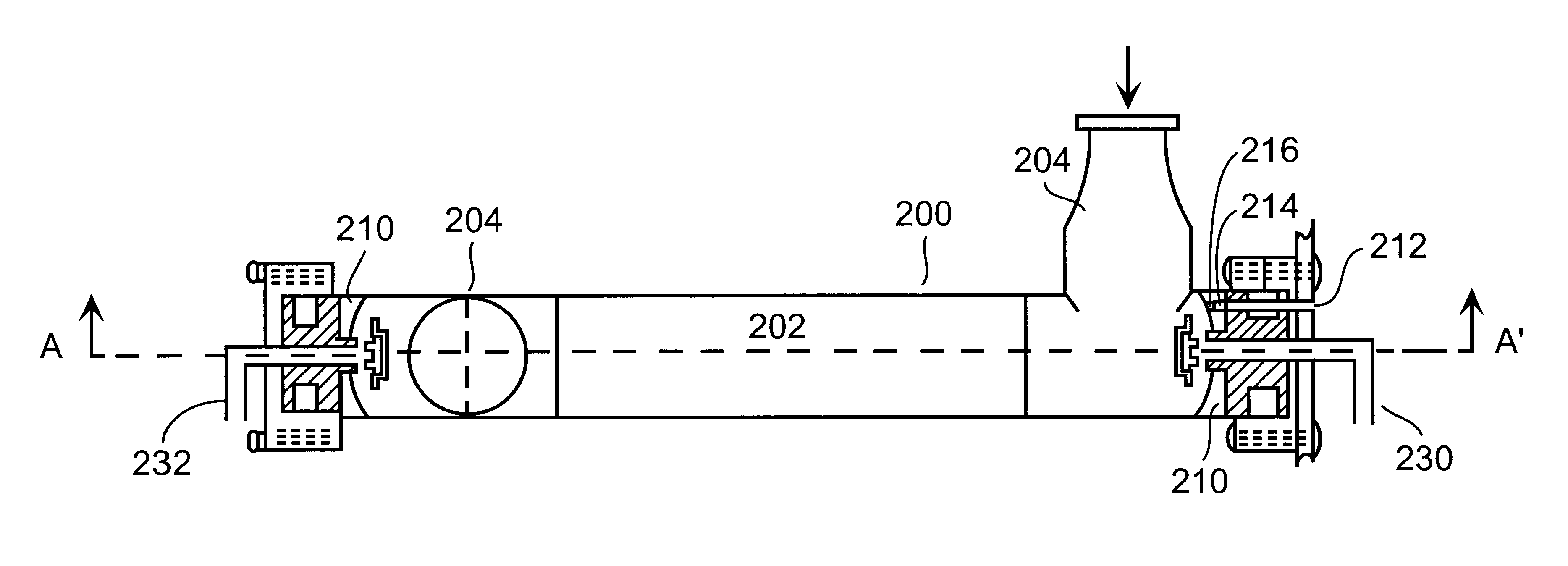
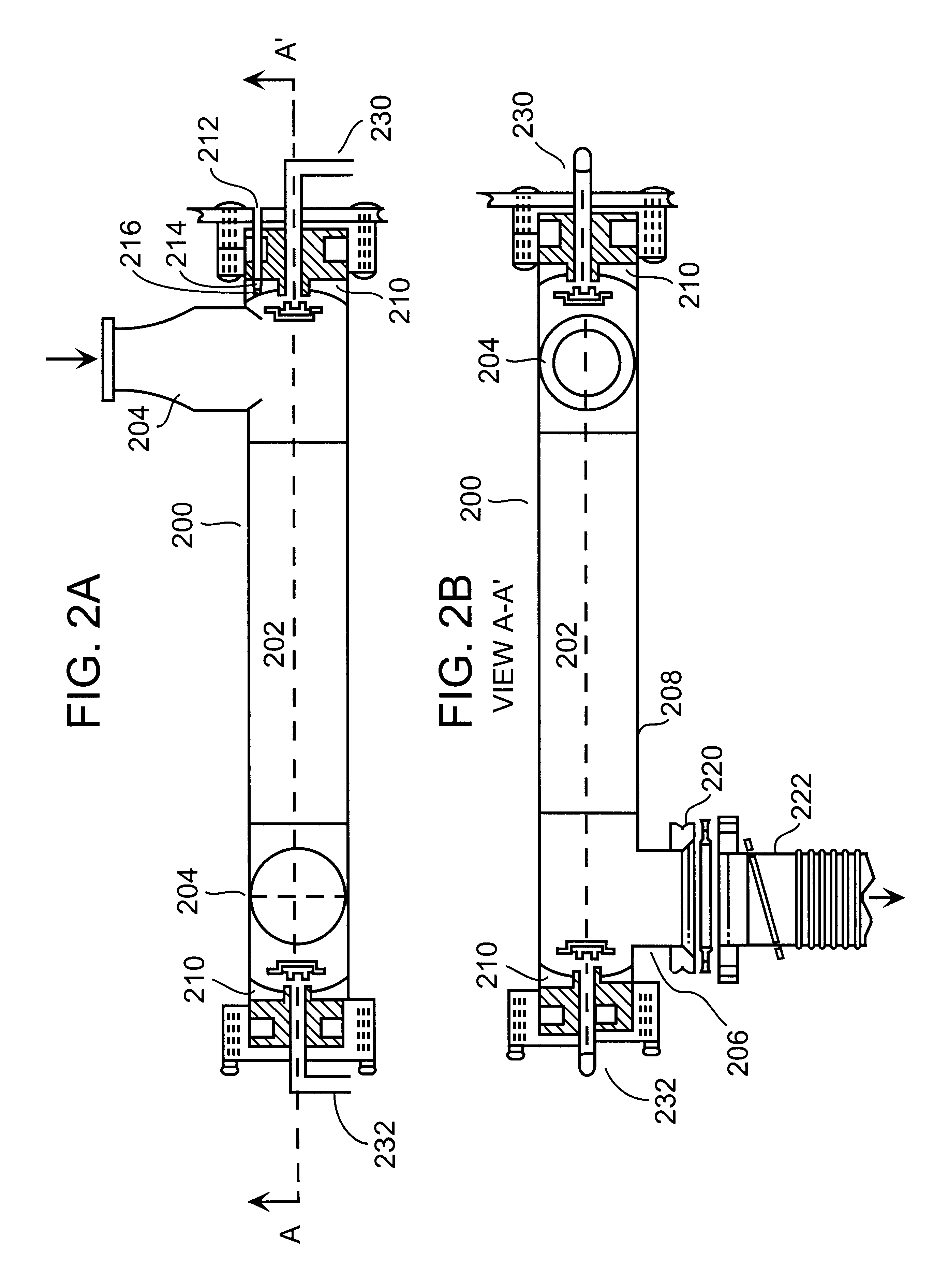
FIGS. 2A and 2B illustrate cross-sectional views of an exemplary in-line cell 200 useful in absorption spectroscopy according to one aspect of the invention. While this exemplary cell is of the Herriott type of multipass cell, it should be clear that the inventive concepts described hereinbelow are in no way limited thereto, and can readily be applied to other forms of cells which employ optical elements, for example, intra-cavity and cavity ring-down cells.

The in-line cell 200 includes a sample region 202. The walls of the cell preferably define a substantially cylindrical space through which the sample gas flows. The sample gas flows through the cell from a sample inlet port 204 into sample region 202, and out of the cell through exhaust port 206.

The inlet port 204 is to be connected to a source of the sample to be measured. As described below, inlet port 204 can advantageously be connected to an exhaust line of a semiconductor processing tool which allows the performance of in-si...


PUM


Abstract

Provided are novel methods of preventing deposition on an optical component in an absorption spectroscopy measurement cell. The methods involve performing an absorption spectroscopy measurement of a sample gas introduced into the cell, and introducing a flow of purge gas from a purge gas inlet pipe across a critical surface of the optical element at a velocity effective to prevent deposition on the critical surface. The gas inlet is disposed adjacent said critical surface. Also provided are devices for practicing the inventive method, measurement cells useful in absorption spectroscopy measurements, apparatuses for performing an absorption spectroscopy measurement and semiconductor processing apparatuses. The invention allows for the performance of accurate spectroscopic measurements. Because deposits are prevented from forming on the surface of an optical element, interference therefrom can effectively be avoided.

Description

1. Field of the InventionThe present invention relates to novel methods and devices for preventing deposition on an optical component in an absorption spectroscopy measurement cell. The present invention also relates to measurement cells useful in absorption spectroscopy measurement. The invention further relates to apparatuses for performing an absorption spectroscopy measurement, and to semiconductor processing apparatuses.2. Description of the Related ArtSemiconductor integrated circuits (ICs) are manufactured by a series of processes, many of which involve the use of gases. Included among such processes are etching, diffusion, chemical vapor deposition (CVD), ion implantation, sputtering and rapid thermal processing. The use of an in-line absorption spectroscopy cell to monitor impurities in such processes is described, for example, in U.S. Pat. No. 5,963,336, to McAndrew et al, the contents of which are incorporated herein by reference.The sensitivity of detection of gas phase ...

Claims


Application Information

Patent Timeline
IPC IPC(8): G01N21/15G01J3/42G01J3/44G02B27/00G01N21/27
CPCG01J3/42G01J3/44G01N21/15G02B27/0006G01J3/0259G01N2021/151B08B17/02
Inventor MCANDREW, JAMES J. F.JURCIK, BENJAMINSCHNEPPER, CAROLINMAN, RONALDZNAMENSKY, DMITRYJACKSIER, TRACEY
Owner LAIR LIOUIDE POUR LETUD ET LEXPL DES PROCEDES GEORCLAUDE
Learn More