
Methods and systems for producing three-dimensional images using relief textures

a technology of relief texture and three-dimensional image, applied in the direction of filling the planer surface with attributes, instruments, computing, etc., can solve the problems of unreachable one-to-one relationship between pixels in original and projected images, flat image creation using conventional methods, and flat reproduction of scenes

Inactive Publication Date: 2002-07-23
NORTH CAROLINA UNIV OF THE
View PDF5 Cites 114 Cited by
  • Summary
  • Abstract
  • Description
  • Claims
  • Application Information

AI Technical Summary

Benefits of technology

The pre-warp equations have a simple one-dimensional structure that enables the pre-warp to be implemented using only one-dimensional image operations along scan lines and columns. In addition, pre-warping requires interpolation between only two adjacent pixels at a time. This allows efficient implementation in software and should allow a simple and efficient hardware implementation. Texture-mapping hardware common in graphics systems may be used to efficiently implement the final texture mapping stage of the warp.
It is another object of the present invention to provide methods and systems for generating three-dimensional images with a convenient inverse formulation and the ability to display the proper occlusion relationships in an image when the viewpoint changes.

Problems solved by technology

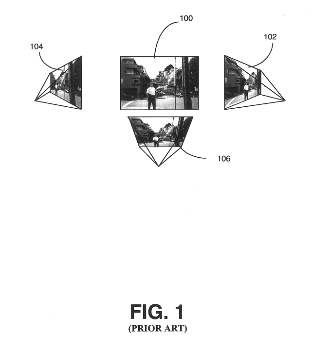
One problem with conventional texture mapping is that images created using conventional methods appear flat when viewed from different viewpoints. FIG. 1 illustrates computer images of a photograph viewed from different viewpoints.
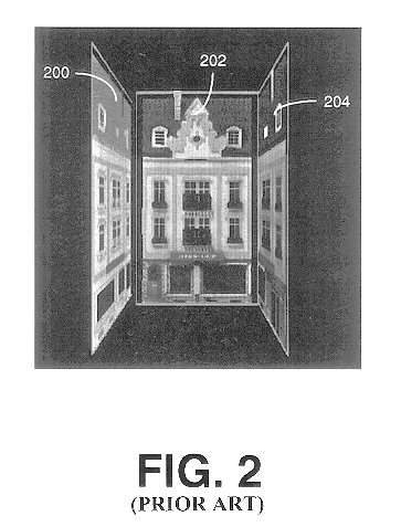
Because the textures do not convey depth information with regard to the actual surfaces they represent, the reproduction of the scene appears flat.
The problem of holes appearing in a warped image is a reconstruction problem, and some action is required to fill such holes.
Another problem with three-dimensional image warping is that the one-to-one relationship between pixels in original and projected images may not hold.
Searching for the closest intersection along the projected ray is computationally expensive and, therefore unsuitable for interactive applications.
In addition, because of the lack of one-to-one correspondence between pixels in the scene and pixels in the image plane, no inverse mapping is readily available.
The lack of a convenient inverse mapping makes filtering difficult.
The main disadvantages of three-dimensional image warping are poor filtering and the appearance of holes.
Unfortunately, however, when a single image with depth is used, areas not visible in the original image may become exposed, producing holes in the final image.
Also, because three-dimensional image warping is usually a many-to-one mapping, it does not have a cheap inverse formulation.
Texture mapping has a simple inverse formulation but does not account for changes in occlusion relationships when views change.
Although this approach is expected to produce smoother rendering than traditional forward mapping (splatting) techniques, the reconstruction is done using splats and holes may still occur.

Method used


Image

  • Methods and systems for producing three-dimensional images using relief textures
  • Methods and systems for producing three-dimensional images using relief textures
  • Methods and systems for producing three-dimensional images using relief textures

Examples


Embodiment Construction

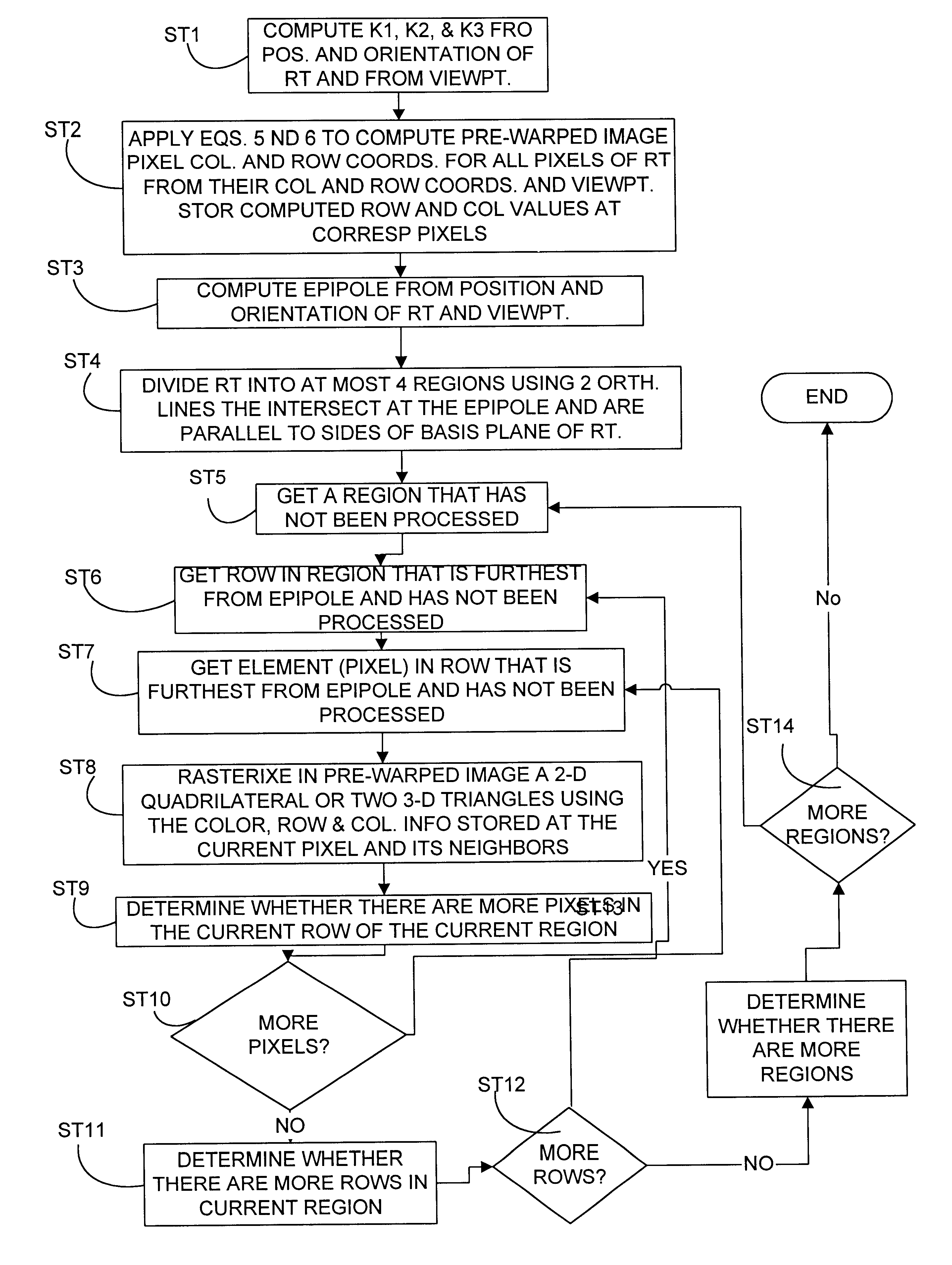
The present invention includes methods and systems for generating three-dimensional images using relief textures. The methods and systems according to the present invention may be implemented in hardware, software, or a combination of hardware and software. FIG. 5 illustrates exemplary steps that may be performed in generating a three-dimensional image according to the present invention. In step ST1, the scene is modeled using one or more relief textures. Once the scene has been modeled, each relief texture is pre-warped to its own basis according to the desired viewpoint. (step ST2) After the images have been pre-warped to basis planes of the relief textures, the pre-warped images are texture mapped onto the associated polygons used to model the scene based on the desired viewpoint. (step ST3) Each of these steps will now be described in more detail.

FIG. 6 illustrates an exemplary scene modeling routine that may be utilized to model a scene according to the present invention. In st...


PUM


Abstract

Methods and systems for producing three-dimensional images of a scene using relief textures include modeling surfaces in a scene with one or more relief textures. Each relief texture is projected onto its basis plane based on a desired viewpoint to produce a pre-warped image. Each pre-warped image is projected onto one or more polygons used to model the scene. Because the steps of texture mapping and pre-warping are separated, solving for visibility during the pre-warping is facilitated by using one-dimensional pre-warping equations

Description

The present invention relates to methods and systems for producing three-dimensional images of a scene. More particularly, the present invention relates to modeling a scene using relief textures, pre-warping the relief textures into two-dimensional textures that are perspectively correct from a desired viewpoint, and texture mapping the two-dimensional textures to polygons used to model the scene.RELATED ARTIn computer graphics, conventional textures are two-dimensional patterns or arrays of pixels used to add detail to computer-generated images. In other words, each pixel in a conventional texture has a row coordinate in texture space, a column coordinate in texture space, and a color value. Texture mapping is the process of mapping two-dimensional textures onto polygons used to model objects displayed on a computer screen. For example, the front of a building may be represented by a rectangle in computer graphics. A texture for the front of the building may include the windows. Te...

Claims


Application Information

Patent Timeline
IPC IPC(8): G06T15/10G06T15/20G06T15/04
CPCG06T15/04G06T2210/44
Inventor BISHOP, THOMAS G.OLIVEIRA NETO, MANUEL M. DE
Owner NORTH CAROLINA UNIV OF THE
Learn More