
Wide bandwidth fiber raman amplifier

a raman amplifier, wide bandwidth technology, applied in the direction of lasers, electromagnetic transmission, transmission, etc., can solve the problems of reducing the bandwidth of prior art raman amplifiers, crosstalk between wavelength division multiplexed (wdm) channels, and weakening the strength and quality of transmitted optical signals, so as to achieve efficient filtering and expand the amplification bandwidth of raman amplifiers

Inactive Publication Date: 2002-07-23
SUBCOM LLC
View PDF4 Cites 41 Cited by
  • Summary
  • Abstract
  • Description
  • Claims
  • Application Information

AI Technical Summary

Benefits of technology

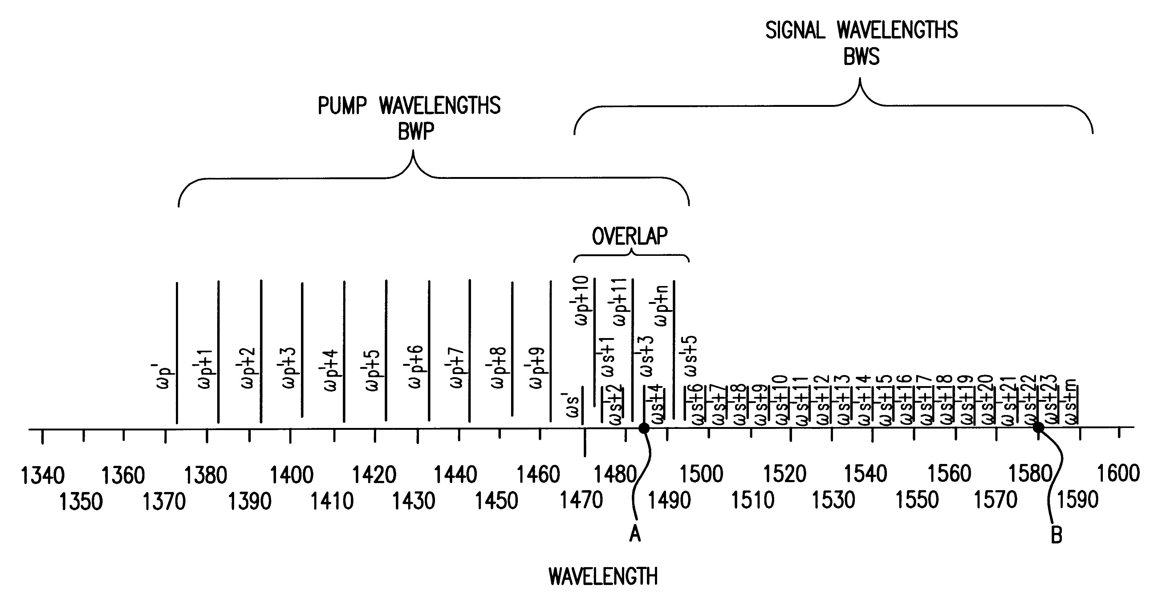
In accordance with the present invention, the amplification bandwidth of a Raman amplifier is expanded by interleaving narrow pump wavelengths between signal wavelengths, thereby avoiding interaction between the signal wavelengths and the BRS of the interleaved pump wavelengths. The line width of the pump signals are narrow enough (e.g., less than 1 GHz) compared to the wavelength spacing of the signal wavelengths (e.g., as low as 25 GHz) so that the BRS of the interleaved pump wavelengths is readily distinguishable from signal wavelengths and can be efficiently filtered out.

Problems solved by technology

Over such long distances, however, the strength and quality of a transmitted optical signal diminishes.
Co-propagating pumps may be used, although a counter-propagation pump scheme reduces polarization sensitivity and cross talk between wavelength division multiplexed (WDM) channels.
Despite multiple pump configurations, prior art Raman amplifiers are nevertheless limited in bandwidth, which in turn limits the capacity of WDM systems.
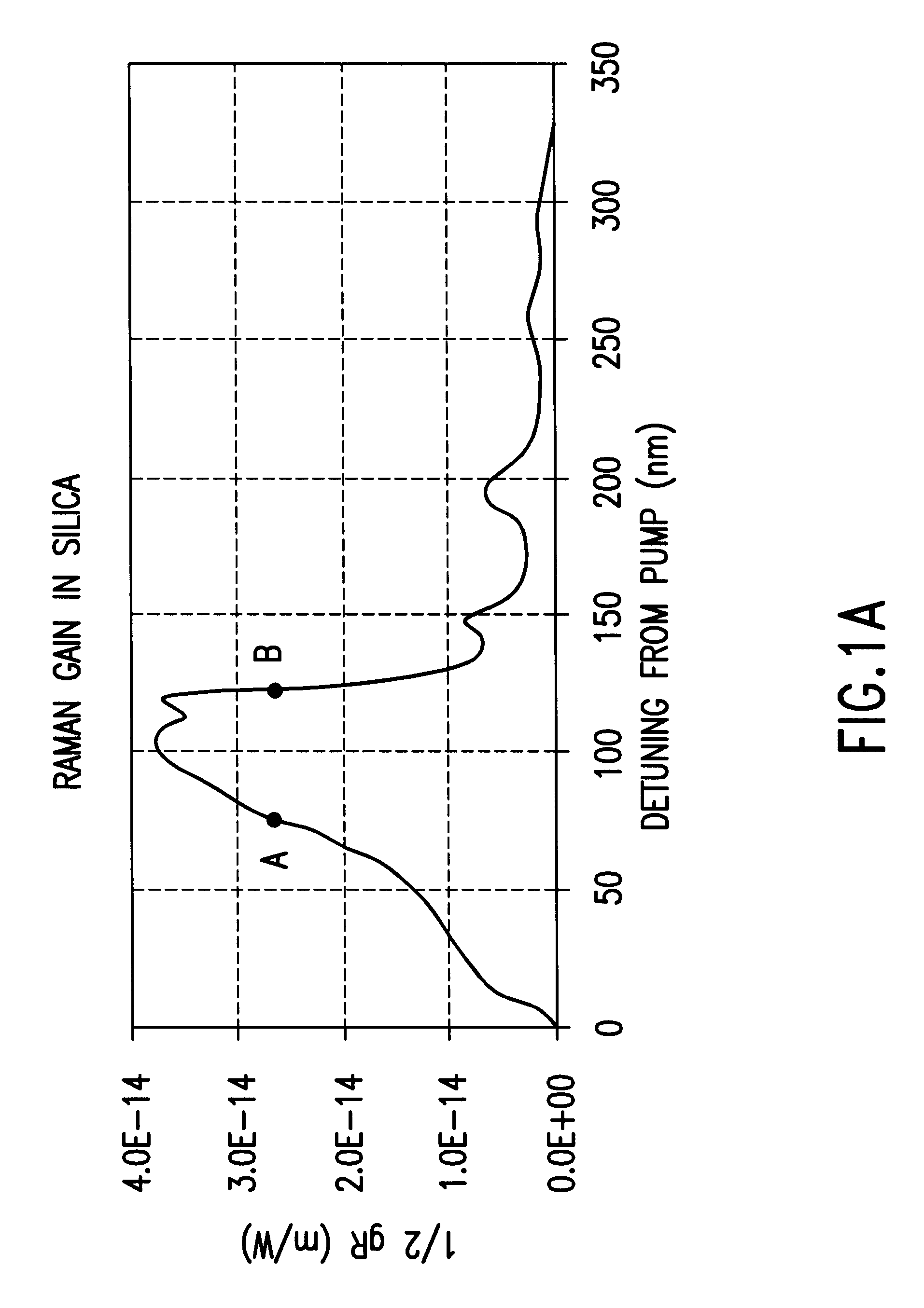
More specifically, because the effective Raman gain tails off at about 125 nm from the pump wavelength, signal wavelengths beyond this point are not effectively amplified.
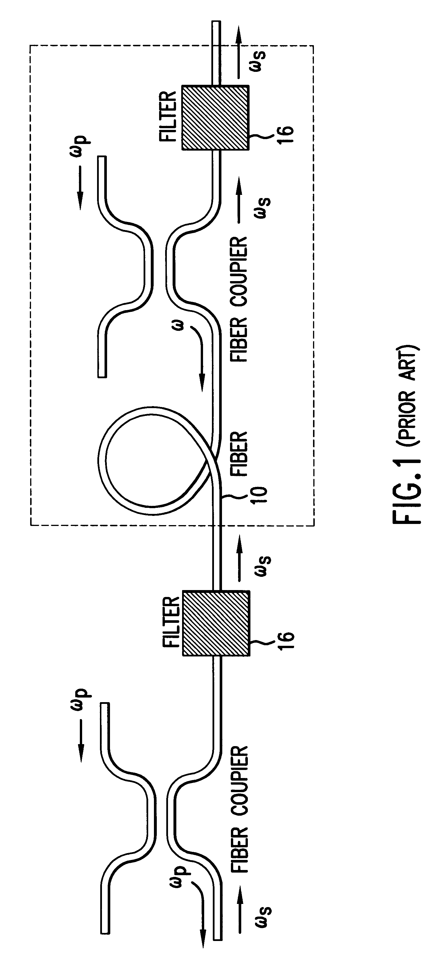
Although the pump and signal wavelengths can be easily separated by filtering in a counter-propagating scheme, the BRS from the pump wavelengths, which propagates in the direction of the signals, is not easily filtered.
The BRS from the pump wavelength at point A is affected by the Raman gain of the lower pump wavelengths, thus introducing undesired noise into the signal wavelengths near point A (FIG. 2).
Thus, BRS both decreases the Raman amplification of the adjacent signals by depleting the pump wavelengths' power, and diminishes signal quality by introducing noise and cross-talk between the channels.
The two side bands may also introduce undesired noise into the signal wavelengths.

Method used


Image

  • Wide bandwidth fiber raman amplifier
  • Wide bandwidth fiber raman amplifier
  • Wide bandwidth fiber raman amplifier

Examples


example

FIG. 5 illustrates the results of a numerical simulation of a Raman amplifier having 120 nm bandwidths. As shown, a gain ripple of less than 0.3 dB is achieved with 38 pump wavelengths (only 10 pump wavelengths are interleaved with signal wavelengths) situated at 4 nm spacing, illustrated by the relatively stable amplitude of the amplified signals at approximately -7 dBm. This numerical simulation is performed for 61 channel signals separated by 2 nm widths, thereby providing -7 dBm (0.2 mW) power per channel. The fiber span is represented as being 50 km long and consisting of standard telecommunication fiber with losses of 0.2 dB / km at 1550 nm. The total span loss at 1550 nm is 10 dB. Pump wavelengths start from 1360 nm (not shown) and end at 1512 nm. Signals start from 1475 nm and end at 1595 nm, covering three telecommunication bands (S, C, and L). The pump power starts at approximately 130 mW per pump and drops to below 10 mW above 1430 nm. Total pump power in the simulation is ...


PUM


Abstract

A method of Raman amplification comprising the step of effecting a plurality of pump wavelengths on a Raman-active transmission medium transmitting counter-propagating signal wavelengths, wherein at least one of said pump wavelengths are interleaved between said signal wavelengths.

Description

FIELD OF THE INVENTIONThis invention pertains to Raman amplifiers and, more particularly, to Raman amplifiers having a bandwidth which exceeds the peak Raman Stokes gain shift of the transmission medium with which the Raman amplifier is utilized.BACKGROUND OF THE INVENTIONOptical fiber technology is currently utilized in communications systems to transfer information, e.g., voice signals and data signals, over long distances as optical signals. Over such long distances, however, the strength and quality of a transmitted optical signal diminishes. Accordingly, techniques have been developed to regenerate or amplify optical signals as they propagate along an optical fiber.One well-known amplifying technique exploits an effect called Raman scattering to amplify an incoming information-bearing optical signal (referred to herein as a "signal wavelength"). Raman scattering describes the interaction of light with molecular vibrations of the material through which the light propagates (refe...

Claims


Application Information

Patent Timeline
IPC IPC(8): H01S3/30H04B10/17H01S3/094H01S3/067H01S3/06H01S3/23
CPCH01S3/302H04B10/2916H01S3/06754H01S3/094003
Inventor DMITRI, FOURSA
Owner SUBCOM LLC
Learn More