Synchronous pipelined switch using serial transmission

Inactive Publication Date: 2002-07-23
CISCO TECH INC
View PDF14 Cites 34 Cited by
  • Summary
  • Abstract
  • Description
  • Claims
  • Application Information

AI Technical Summary

Problems solved by technology

One problem in the known art is that, for the switch to operate on parallel data, it will require a very large number of incoming and outgoing communication paths for individual message bits.
However, if the switch is at all sizable, this makes connectivity with the swit

Method used


Image

  • Synchronous pipelined switch using serial transmission
  • Synchronous pipelined switch using serial transmission
  • Synchronous pipelined switch using serial transmission

Examples


Embodiment Construction

In the following description, a preferred embodiment of the invention is described with regard to preferred process steps and data structures. Those skilled in the art would recognize after perusal of this application that embodiments of the invention can be implemented using circuitry or other elements adapted to particular process steps and data structures, and that implementation of the process steps and data structures described herein would not require undue experimentation or further invention.

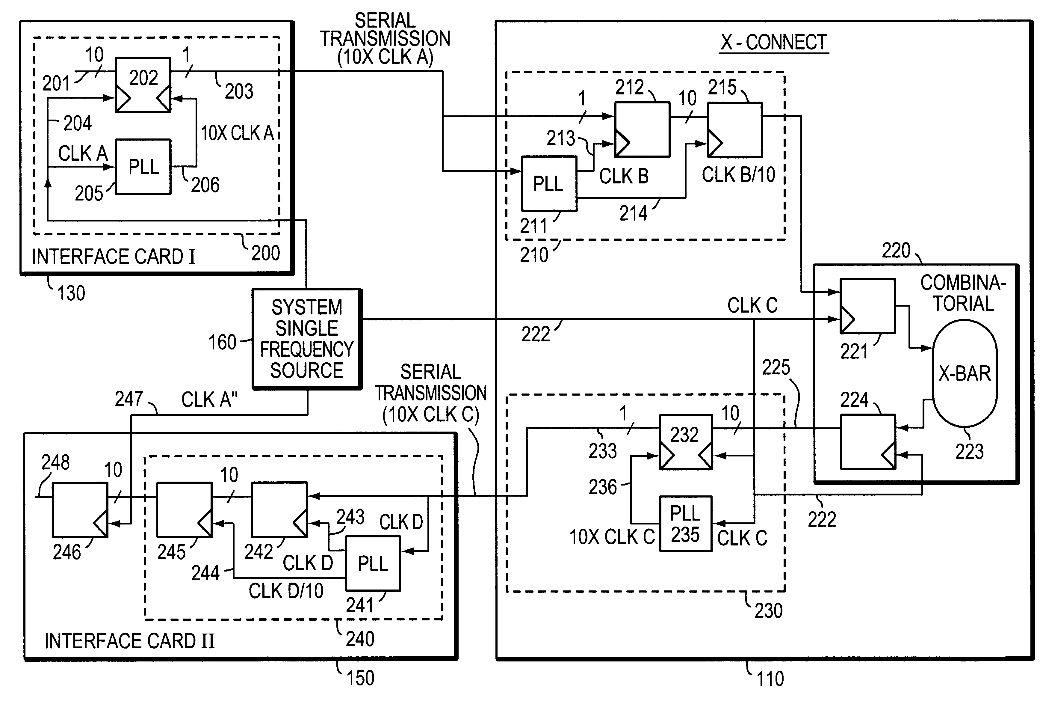
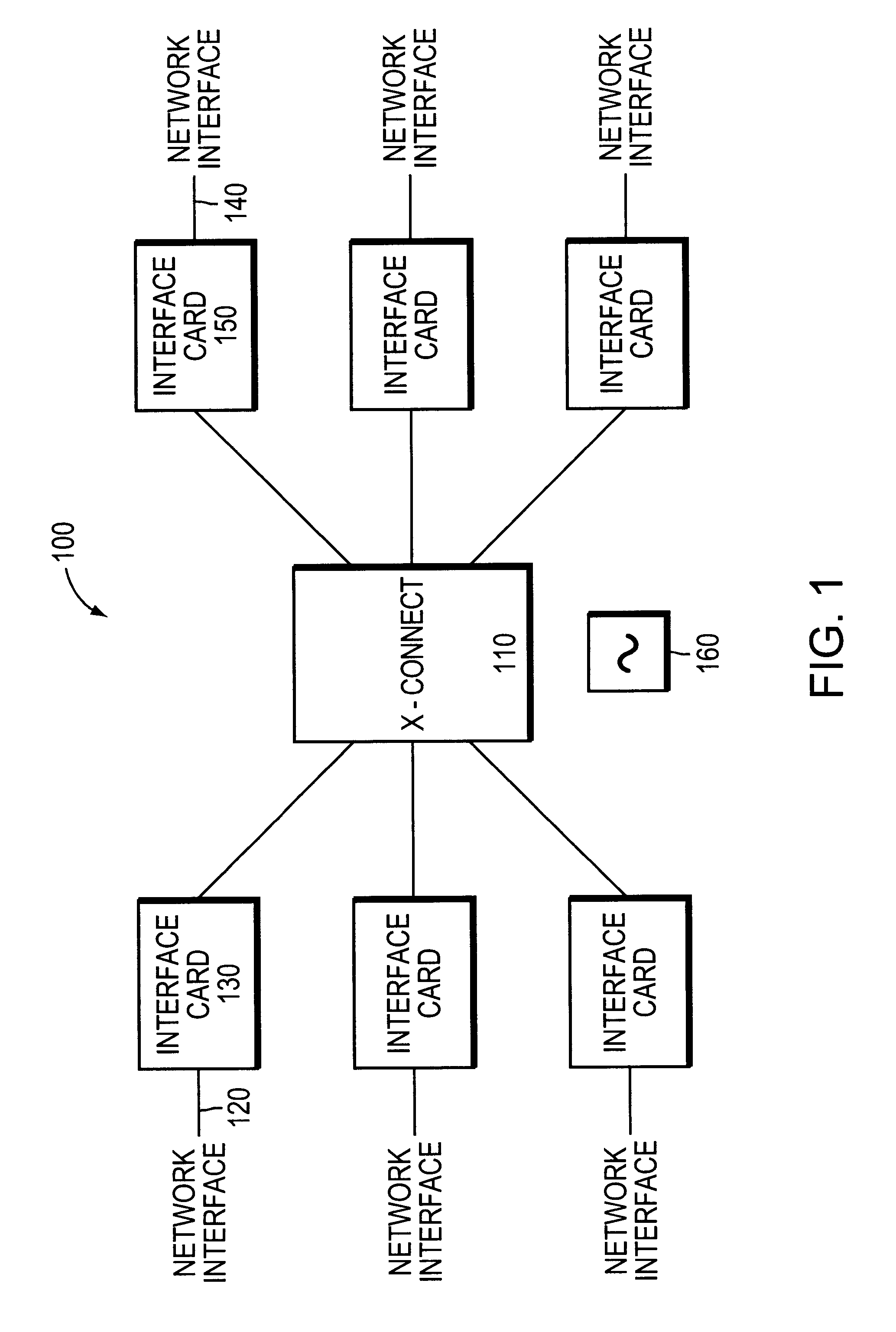
FIG. 1 shows a block diagram of an interconnect system.

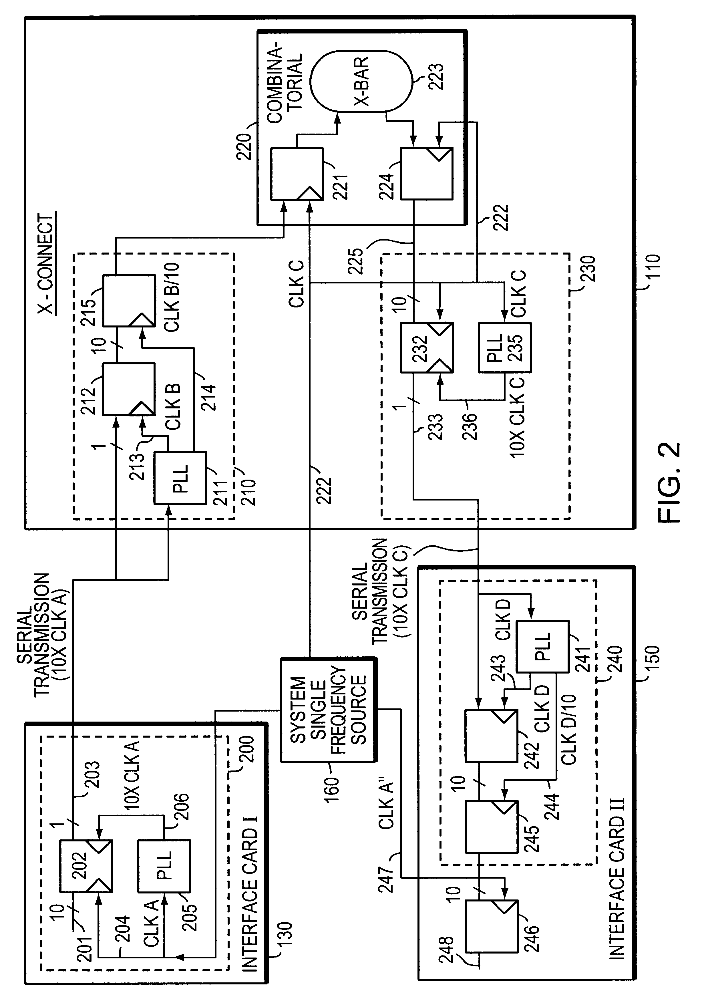
An interconnect system 100 includes a switch interconnect 110, a plurality of input ports 120, a plurality of input interfaces 130 each corresponding to at least one input port 120, a plurality of output ports 140, a plurality of output interfaces 150 each corresponding to at least one output port 140, and a single frequency source 160.

Incoming data is segmented into fixed size data cells and the system 100 provides the capability to...


PUM


Abstract

The invention provides a method and system for operating a switch, in which incoming data cells are converted from parallel to serial for synchronous input to a switch interconnect, converted from serial to parallel for parallel switching, converted from parallel to serial for synchronous output from the switch interconnect, and converted from serial to parallel for output. The switch interconnect and its input and output interfaces are controlled by a single frequency source, so that all serial data communication paths into and out of the switch interconnect are phase synchronized to within one clock cycle. A single frequency source for the switch system is coupled to the input interfaces, to output interfaces, and to the switch interconnect. The input interfaces each include a PLL which synchronizes to the single frequency source once for all serial communication to the switch interconnect. The switch interconnect includes one PLL for each input interface which synchronizes to the serial input from that input interface, and one PLL for each output interface which synchronizes to the single frequency source once for all serial communication to the output interface. Similarly, the output interfaces each include a PLL which synchronizes to the serial output from the switch interconnect. The switch interconnect is coupled to the single frequency source and operates in phase therewith.

Description

1. Field of the InventionThis invention relates to communication switching.2. Related ArtIn switching in communication networks, one important feature is speed. It is generally desirable for switches in such networks to operate as quickly and with as little latency as possible. One method by which switches are known to operate quickly is to synchronously switch individual cells of messages; thus, each cell to be switched is the same length and the switch operates at the start of each cell time to transfer cells from assigned input queues to assigned output queues.One problem in the known art is that, for the switch to operate on parallel data, it will require a very large number of incoming and outgoing communication paths for individual message bits. However, if the switch is at all sizable, this makes connectivity with the switch, and the switch backplane itself, extremely unwieldy and expensive. For example, to support 16 input queues and 16 output queues each operating at 3.2 gi...

Claims


Application Information

Patent Timeline
IPC IPC(8): H04L12/56H04J3/06H04L12/54H04L12/70H04L12/931H04L12/933
CPCH04L12/5601H04L49/106H04L49/608H04J3/0685H04L2012/5674
Inventor LAOR, MICHAELEPPS, GARRY P.
Owner CISCO TECH INC
Why Eureka
Try Eureka