Method and apparatus for providing pseudo-3D rendering for virtual reality computer user interfaces

a virtual reality computer and user interface technology, applied in the field of pseudo-3d rendering for virtual reality computer user interfaces and data processing systems, can solve problems such as visual discontinuity, break the "place" paradigm, and assume a fixed viewing angle and siz

Inactive Publication Date: 2002-07-30
ACTIVISION PUBLISHING
View PDF28 Cites 115 Cited by
  • Summary
  • Abstract
  • Description
  • Claims
  • Application Information

AI Technical Summary

Problems solved by technology

While the use of 3D drawings can be used on sufficiently equipped systems that have powerful microprocessors or add-on devices to process the complex 3D images, this computational overhead on the most popular personal computers (PC) systems are wanting in the ability to render 3D drawings on the fly in their full complexity.
Unfortunately, when a 2D image is created for an object, it assumes a fixed viewing angle and size.
While an object may be correctly drawn so that it appears correct in one place, moving the object to a different location in a 3D world results in visual discontinuity and breaks the "place" paradigm.
Unfortunately, the world itself is static in this implementation and needs more interactive characteristics by adding visual representations of objects contained in the computer.
Unfortunately, adding objects anywhere in the virtual world requires the object to be drawn in the proper viewing angle.
This is a problem for 2D-based systems because of all of the possible viewing angles and surfaces upon which objects may be attached or laid.
Thus, if a wall clock is placed on the wall at point 3 in FIG. 1, it will appear in the familiar front or orthogonal view for user C's view; however, if it is placed at points 1 or 2, a different view is required for location A or C. Furthermore, the 3D space and grid techniques cannot guarantee a fixed number of viewing angles.

Method used


Image

  • Method and apparatus for providing pseudo-3D rendering for virtual reality computer user interfaces
  • Method and apparatus for providing pseudo-3D rendering for virtual reality computer user interfaces
  • Method and apparatus for providing pseudo-3D rendering for virtual reality computer user interfaces

Examples


Embodiment Construction

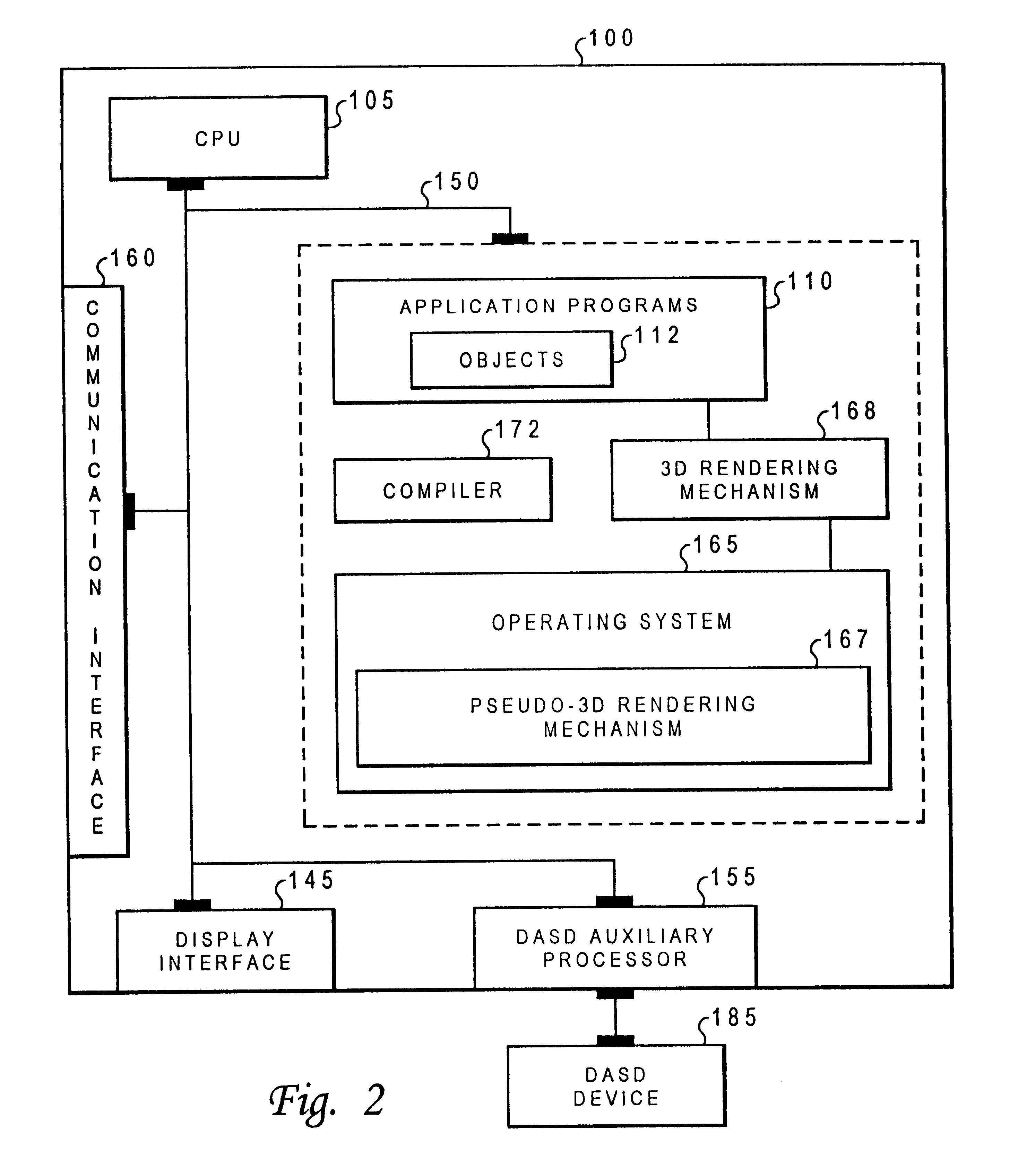
FIG. 2 shows a block diagram of the computer system of the present invention. The computer system of the preferred embodiment is an enhanced IBM Aptiva personal computer system. Those skilled in the art, however, will appreciate that the mechanisms and apparatus of the present invention apply equally to any computer system, regardless of whether the computer system is a complicated multiuser computing apparatus or a single-user workstation. As shown in the exploded view of FIG. 2, computer system 100 comprises main or central processing unit (CPU) 105 connected to main memory 140, terminal interface 145, mass storage interface 155, and network interface 160. These system components are interconnected through this use of system bus 150. Although computer system 100 is shown to contain only a single main CPU and a single system bus, it should be understood that the present invention applies equally to computer systems that have multiple CPUs and to computer systems that have multiple ...


PUM


Abstract

A computer system which includes a central processing unit, a bus, and a memory store coupled to the central processing unit that includes a psuedo 3D rendering mechanism. Typically, the rendering mechanism is loaded in the memory store, but can be implemented in an application's specific integrated circuit further coupled to the central processing unit via the bus. The psuedo 3D rendering mechanism is used to generate a psuedo 3D rendered virtual image using only two dimensional prerendered selected views of 3D objects to be displayed. As the viewing orientation shifts from point to point, an adequate three-dimensional rendering is provided based on these selected views. These selected views are designed for display on a display device further connected to the computer system.

Description

1. Technical FieldThe present invention relates generally to a data-processing system utilizing three-dimensional rendering and, more particularly, to a data-processing system using rendered two-dimensional images for generating pseudo-three-dimensional views. More particularly still, the present invention is directed towards utilizing selected prerendered views of objects in a manner sufficient to provide adequate viewability as well as providing image scaling to provide correct depth perception of the prerendered three-dimensional views.2. Description of the Related ArtComputer systems are well known to those skilled in the art. In fact, computers have become quite common in both the business world and at home. Computers are used because of their ability to perform complex tasks quickly and efficiently. The computers programs, or software, which include the user interfaces, have advanced from character-based user interfaces to graphical-oriented user interfaces, also known as grap...

Claims


Application Information

Patent Timeline
Patent Type & Authority Patents(United States)
IPC IPC(8): G06T15/10G06T15/20
CPCG06T15/205
Inventor SMITH, ANDREW J.WILSON, LESLIE ROBERT
Owner ACTIVISION PUBLISHING
Why Eureka
Try Eureka