Wiper blade for automobile glass panels

a technology for windshield wipers and automobile glass panels, which is applied in the direction of vehicle maintenance, vehicle cleaning, cleaning equipment, etc., can solve the problems of unsatisfactory wiper results and two demands that are practically impossible to m

Inactive Publication Date: 2002-08-06
ROBERT BOSCH GMBH
View PDF11 Cites 47 Cited by
  • Summary
  • Abstract
  • Description
  • Claims
  • Application Information

AI Technical Summary

Benefits of technology

In the wiper blade defined by the body of claim 1, conversely, a choice of material that meets the demands made of each component can be made for both the retaining rail and the connection device. The joining of the two components to one another is done without problems and inexpensively by forming the connection device onto the prefabricated retaining rail. The forming-on is attained by placing the retaining rail in a casting mold or injection mold, which after closure is filled with a plastic that meets the demands. The retaining rail is then provided with the required connection device, and no further assembly steps are needed. Experiments have shown that by the forming on of the connection device, a sufficiently solid connection is made between the connection device and the retaining rail.An especially reliable connection between the retaining rail and the connection device is attained if the connection device is provided with clawlike extensions, which at least intermittently clasp the two side longitudinal edges of the retaining rail and rest on the band face, toward the window, of the retaining rail.If the retaining rail is provided with shoulders, with which counterpart shoulders of the connection device are associated, then an absolutely immobile connection, secured against shifting, is obtained between the retaining rail and the connection device, because counterpart shoulders occur automatically in the molding of the connection device and cooperate with the shoulders of the retaining rail.The shoulders can be embodied in simple way at apertures and / or recesses open at the edge and / or shaped hooklike features of the support element.A further improvement in the fastening of the connection device to the retaining rail is achieved by roughened features, which are provided at least on the surfaces of the retaining rail that are oriented toward the connection device.An especially compact wiper blade is obtained if the retaining rail is made from a metal.In order to provide the retaining rail with a connection device for the wiper arm in an economical way and in the process ideally satisfy the contradictory demands of the retaining rail and the connection device, a fastening method according to the invention is used, in which the prefabricated retaining rail is placed in a mold, which after closure is filled with hardenable plastic, so that after the mold is opened, the finished support element can be removed.Further advantageous refinements and embodiments of the invention are disclosed in the ensuing description of an exemplary embodiment shown in the associated drawing and in a drawing figure that explains the claimed and described production method.

Problems solved by technology

If the retaining rail is to be made of metal, however, two diametrically contradictory demands are involved.
These two demands are practically impossible to meet, unless disadvantageous compromises in terms of the choice of material are made.
The requisite bores in the retaining rail, however, lead to an undesired, because uncontrollable, change in the retaining rail tension, making a satisfactory wiper outcome unattainable.

Method used


Image

  • Wiper blade for automobile glass panels
  • Wiper blade for automobile glass panels
  • Wiper blade for automobile glass panels

Examples


Embodiment Construction

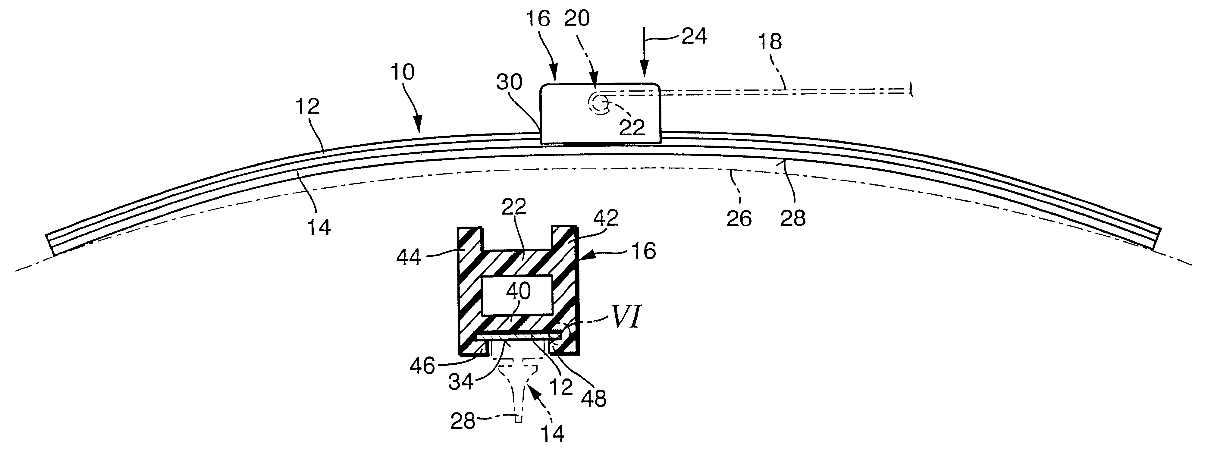
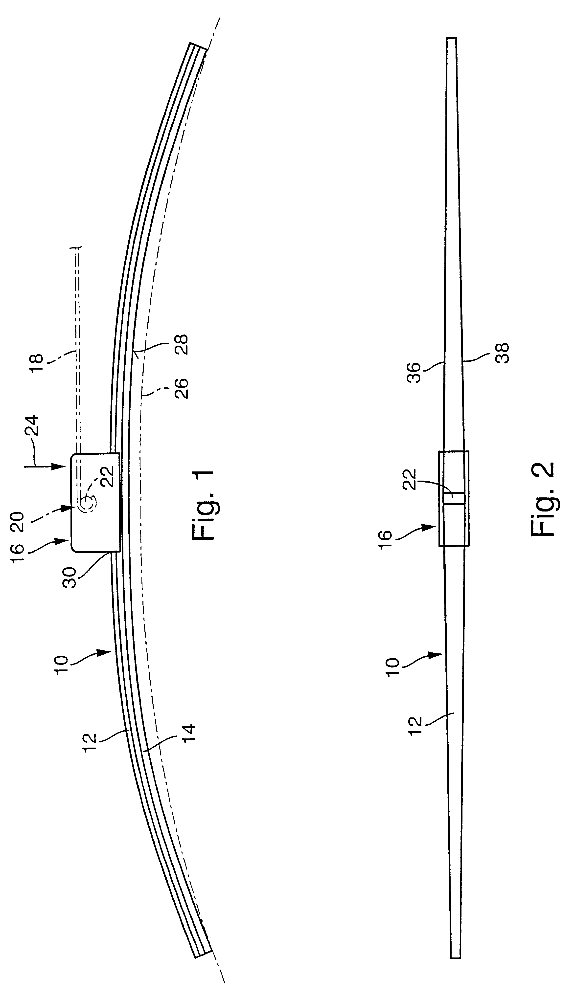
A wiper blade 10 shown in FIGS. 1 and 2 has an elongated, spring-elastic retaining rail 12, to the underside of which an elongated, rubber-elastic wiper strip 14 is secured, parallel to the longitudinal axis. In the middle portion of the top side of the retaining rail 12, which is made of a spring-elastic material, there is a connection device 16, with the aid of which the wiper blade can be separately connected pivotably to a driven wiper arm 18. The wiper arm is guided by one end, not shown, on a vehicle body. A hook acting as a counterpart connection means is formed onto the other, free end 20 of the wiper arm 18 and clasps a pivot bolt 22 (FIG. 1) belonging to the connection device 16 of the wiper blade. The securing between the wiper arm 18 and the wiper blade 10 is taken on by securing means, not shown in detail but known per se and embodied as adapters. The wiper arm 18 and thus the wiper blade as well are urged in the direction of the arrow 24 toward the window to be wiped, ...


PUM

PropertyMeasurementUnit
contact pressureaaaaaaaaaa
pressureaaaaaaaaaa
radii of curvatureaaaaaaaaaa

Abstract

A wiper blade is proposed that is used to clean windows of motor vehicles. The wiper blade (10) has an elongated, rubber-elastic wiper strip (14), which is retained, substantially parallel to the longitudinal axis, on a support element (30) that has a spring-elastic retaining rail (12) elongated in bandlike fashion and a connection device (16) disposed on the retaining rail, in which the connection device (16) is disposed on the band face (32), remote from the window, on the middle portion of the retaining rail (12) and serves to connect the wiper blade (10) to a driven wiper arm that can be stressed toward the window. Advantages in terms of both production and use are obtained if the connection device (16), made from a plastic, is formed directly and immovably onto the retaining rail.

Description

PRIOR ARTIn wiper blades for windows of motor vehicles having elongated, rubber-elastic wiper strips which are pressed against the window to be wiped and which is retained on a support element that has an elongated, bandlike spring-elastic retaining rail, the retaining rail is intended to assured the most uniform possible distribution, over the entire field swept by the wiper blade, of the contact pressure of the wiper blade on the window, which pressure originates in the wiper arm. Because of an appropriate curvature of the unstressed retaining rail--that is, when the wiper blade is not resting on the window--the ends of the wiper strip, which in wiper blade operation are placed fully against the window, are urged by the then-tensed retaining rail toward the window, even if the radii of curvature of spherically curved vehicle windows differ in each wiper blade position. Accordingly, the curvature of the wiper blade has to be somewhat greater than the greatest curvature measured in ...

Claims


Application Information

Patent Timeline
Patent Type & Authority Patents(United States)
IPC IPC(8): B60S1/38B60S1/32B60S1/40
CPCB60S1/38B60S1/3858B60S1/4006B60S1/3855Y10T29/49622B60S2001/382B60S1/3867
Inventor KOTLARSKI, THOMAS
Owner ROBERT BOSCH GMBH
Why Eureka
Try Eureka