Cutting tool retainer

a technology of cutting tool and retainer, which is applied in the direction of snap fasteners, buckles, soil shifting machines/dredgers, etc., can solve the problems of reducing the contact area disengaging the retainer, and difficult installation and removal of the retainer type, so as to reduce or eliminate the movement of the cutting tool with respect to the support block. , the effect of significant strength and durability characteristics

Inactive Publication Date: 2002-08-06
KENNAMETAL INC
View PDF22 Cites 39 Cited by
  • Summary
  • Abstract
  • Description
  • Claims
  • Application Information

AI Technical Summary

Benefits of technology

Furthermore, the retainer body may include additional protruding portions. For example, the retainer body may include at least two or at least three protruding portions extending radially from the main portion. Such additional protruding portions may be used to improve contact between the retainer body and an installation/removal device.
Preferably...

Problems solved by technology

This type of retainer is relatively difficult to move in order to disengage the retainer from the cutting tool in that a screwdriver or other similar object must be inserted into the recess and under the top of the retainer in order to pry and move the retainer.
However, this type of retainer is difficult to install and remove.
More specifically, this retainer d...

Method used


Image

  • Cutting tool retainer
  • Cutting tool retainer
  • Cutting tool retainer

Examples


Embodiment Construction

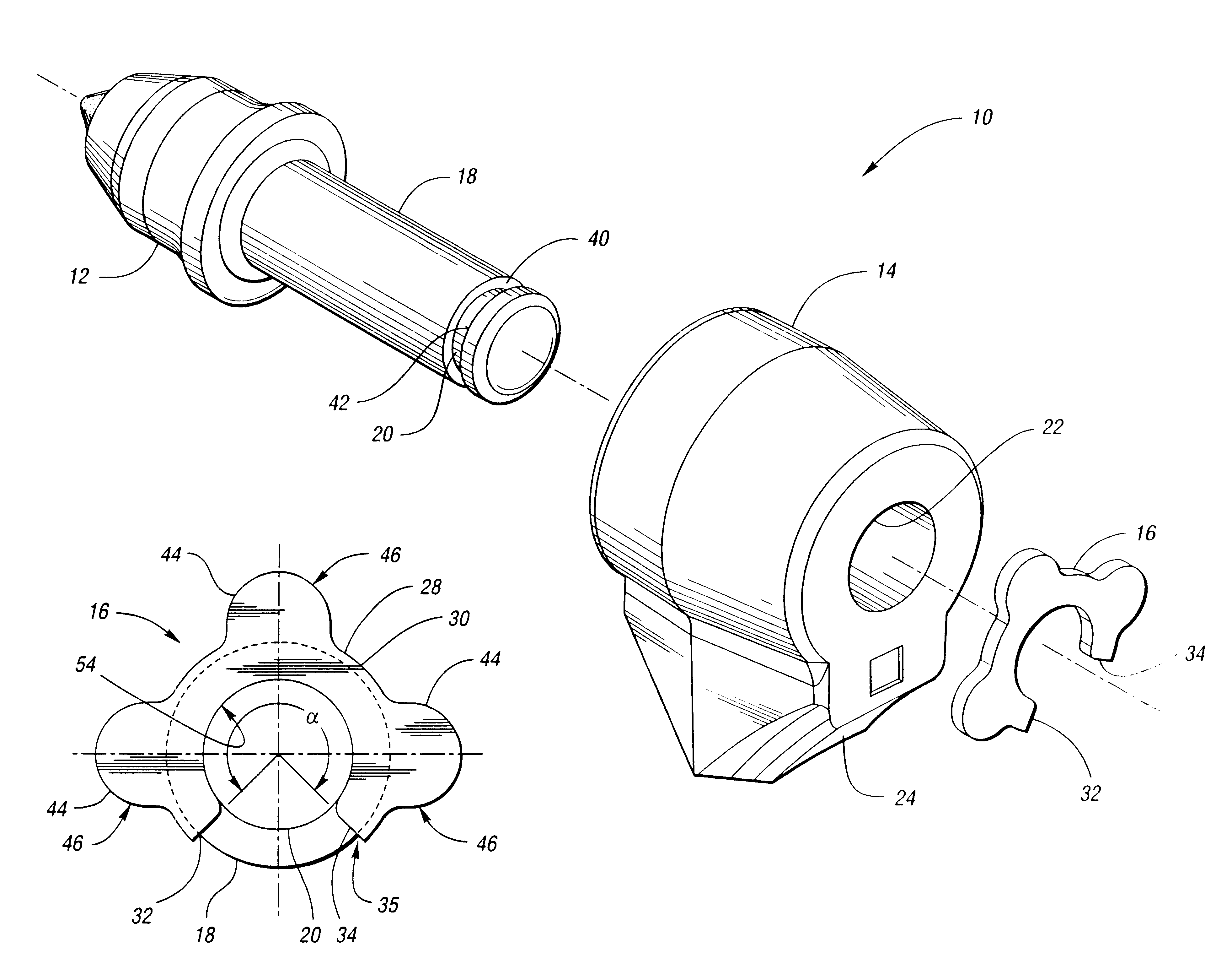
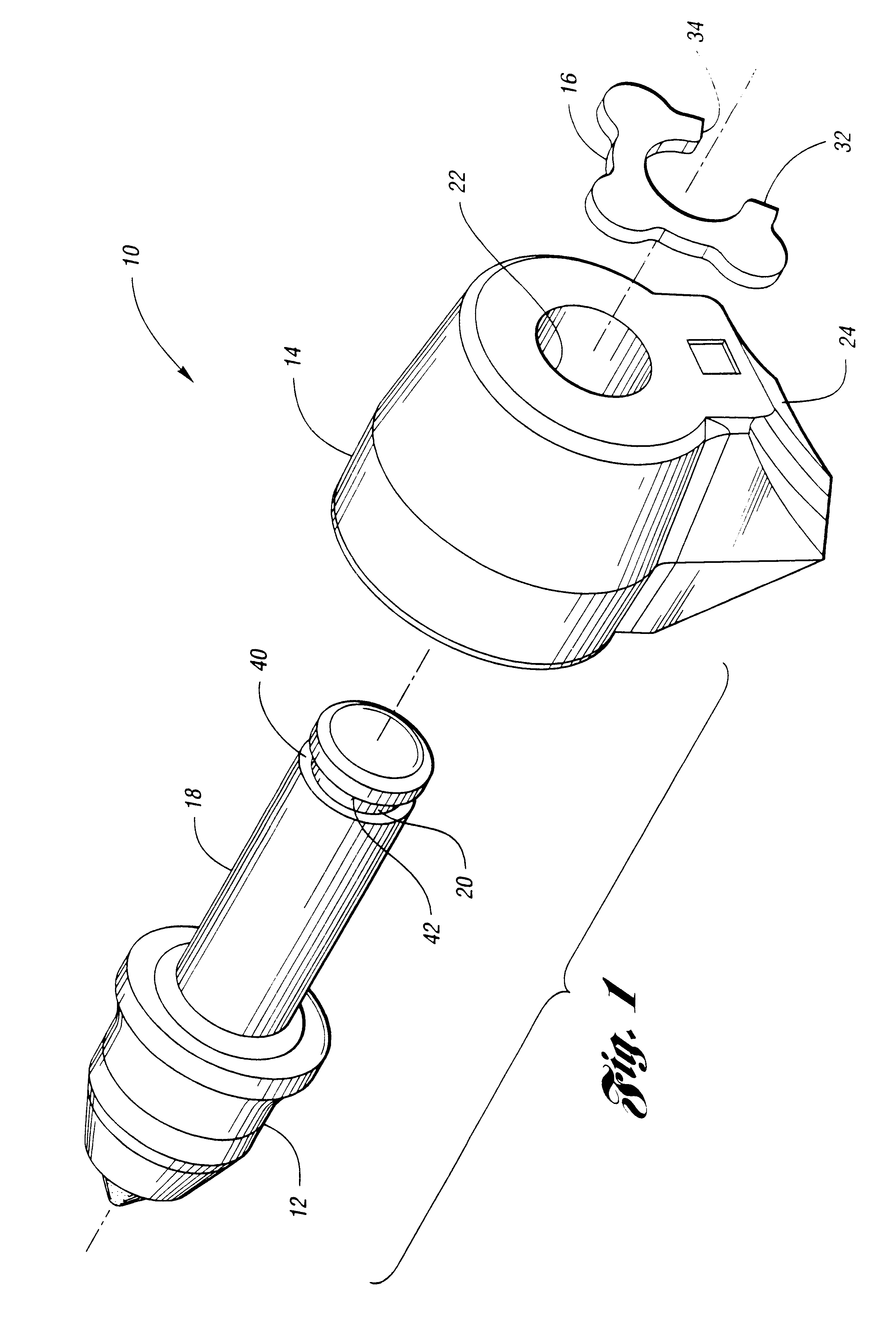
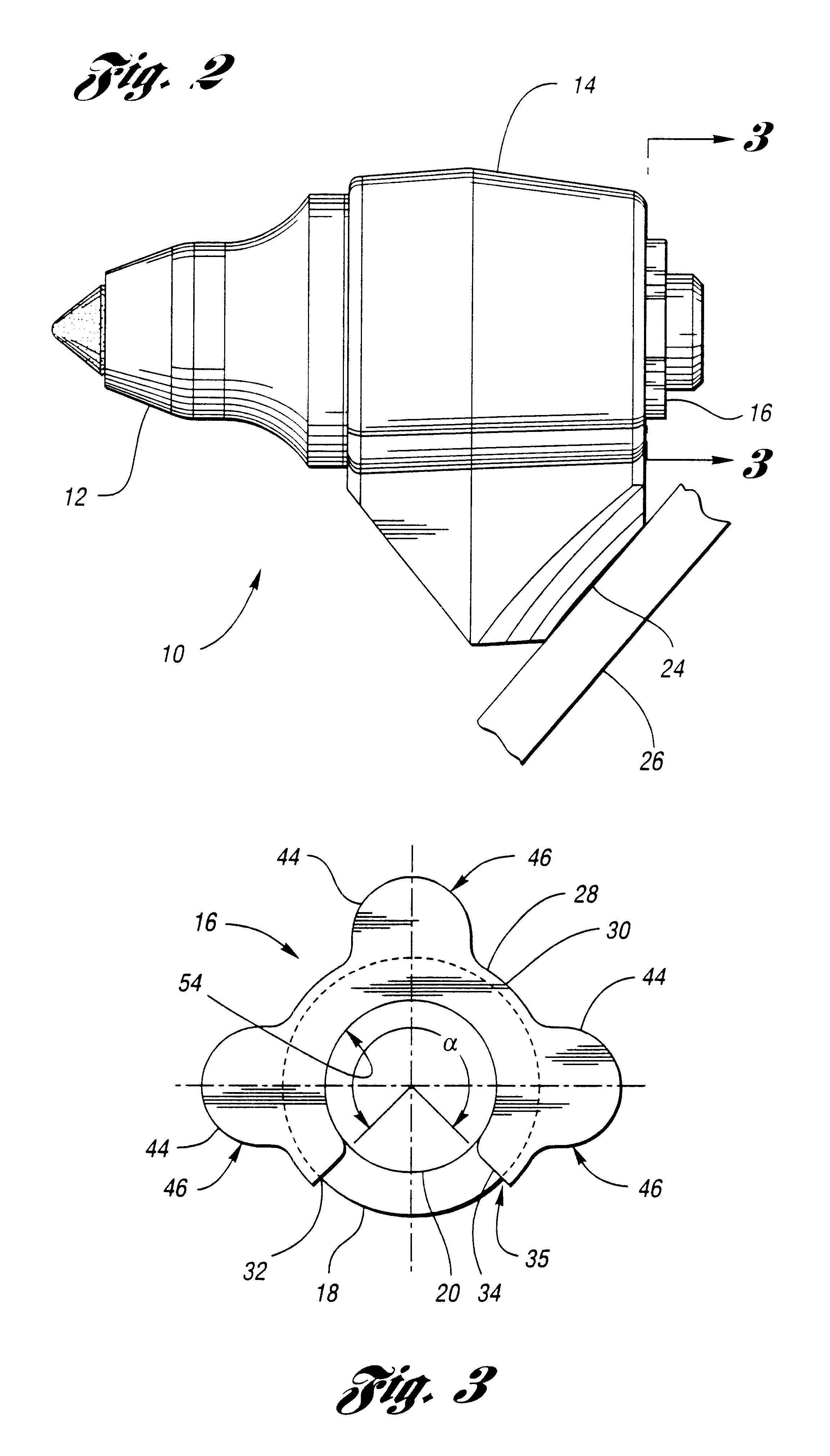
Referring to the drawings, FIGS. 1 and 2 show a cutting tool assembly 10 including a cutting tool 12, a support block 14 and a retainer 16 according to the invention. The cutting tool 12 has a preferably cylindrical shank 18 with an annular groove or recess 20 for receiving the retainer 16. The support block 14 has a preferably cylindrical bore 22 for receiving the shank 18, and a base 24 that can be welded or otherwise attached to a track pad 26 of a trenching machine (not shown). When the track pad 26 is driven by the trenching machine, the cutting tool 12 will engage and break up material sought to be mined or removed. Alternatively, the support block 14 may be welded or otherwise attached to a drum (not shown) or any other suitable body.

Referring to FIGS. 3 and 4, the retainer 16 has a retainer body 28. The retainer body 28 has a main portion such as a curved portion 30 having first and second ends 32 and 34, respectively. The curved portion 30 defines an arc preferably extendin...


PUM


Abstract

A retainer, adapted to engage a recess in a cutting tool for securing the cutting tool to a support block, includes a retainer body having a main portion with first and second ends. The main portion defines a continuous shear zone having first and second ends. The retainer body further includes a protruding portion disposed between the ends of the continuous shear zone and spaced away from the ends of the main portion. The protruding portion extends radially from the main portion and is adapted to overlap the support block when the retainer is engaging the recess.

Description

The invention relates to a retainer for retaining a cutting tool in a support block.Cutting tool assemblies for such applications as mining or road milling typically comprise a cutting tool, sometimes referred to as a cutting pick, rotatably mounted within a support block. The support block in turn is mounted onto a drum or other body, typically by welding, which in turn is driven by a suitable drive means. When a number of such support blocks carrying cutting tools are mounted onto a drum, and the drum is driven, the cutting tools will engage and break up the material sought to be mined or removed. The general operation of such a mining or construction machine is well known in the art.Various retainers have been proposed or used to mount a cutting tool, rotatably or otherwise, within a support block. For example, U.S. Pat. No. 4,505,058 to Peterson shows a retainer having two legs. This retainer is intended to be used with a support block having a recess with specially configured s...

Claims


Application Information

Patent Timeline
IPC IPC(8): E02F9/28E21C35/00E21C35/197E21C35/18
CPCE02F9/2866E21C35/197Y10T24/45832E21C2035/1826E21C35/188
Inventor RITCHEY, CARY D.STIFFLER, STEPHEN P.
Owner KENNAMETAL INC
Why Eureka
Try Eureka