Differential-input circuit

a differential input and input circuit technology, applied in the field of circuits, can solve the problems of increasing the size of the mos control logic accordingly, increasing the power consumption of the mos control logic, so as to maintain the area efficiency and low power consumption

Inactive Publication Date: 2002-08-06
INT BUSINESS MASCH CORP
View PDF7 Cites 3 Cited by
  • Summary
  • Abstract
  • Description
  • Claims
  • Application Information

AI Technical Summary

Benefits of technology

The present invention provides a differential reduced-swing input voltage to a differential-input circuit for outputting a differential logic signal. The present invention further provides a differential-input circuit which maintains area efficiency and low power consumption.

Problems solved by technology

Further, as the functions of the high speed communication circuits become complicated, the size of the MOS control logic grows accordingly larger.
A larger area interface circuit creates disadvantages, such as more power consumption.
Furthermore, the MOS control logic consumes more power not only when it has a larger area, but by its nature, this kind of circuit consumes static power.
To generate an intermediate voltage level in an interface to the ECL circuit, static power consumption through the resistors and transistors is unavoidable unless an external reference voltage is supplied.

Method used


Image

  • Differential-input circuit
  • Differential-input circuit
  • Differential-input circuit

Examples


Embodiment Construction

The present invention will be described in terms of illustrative circuits. It is to be understood that these circuits are described with particular values for parameters, such as voltage, current, resistance, component sizes, etc. These values are illustrative and should not be construed as limiting the present invention.

Referring now in detail to the drawing in which like reference numerals identify similar or identical elements throughout the drawings.

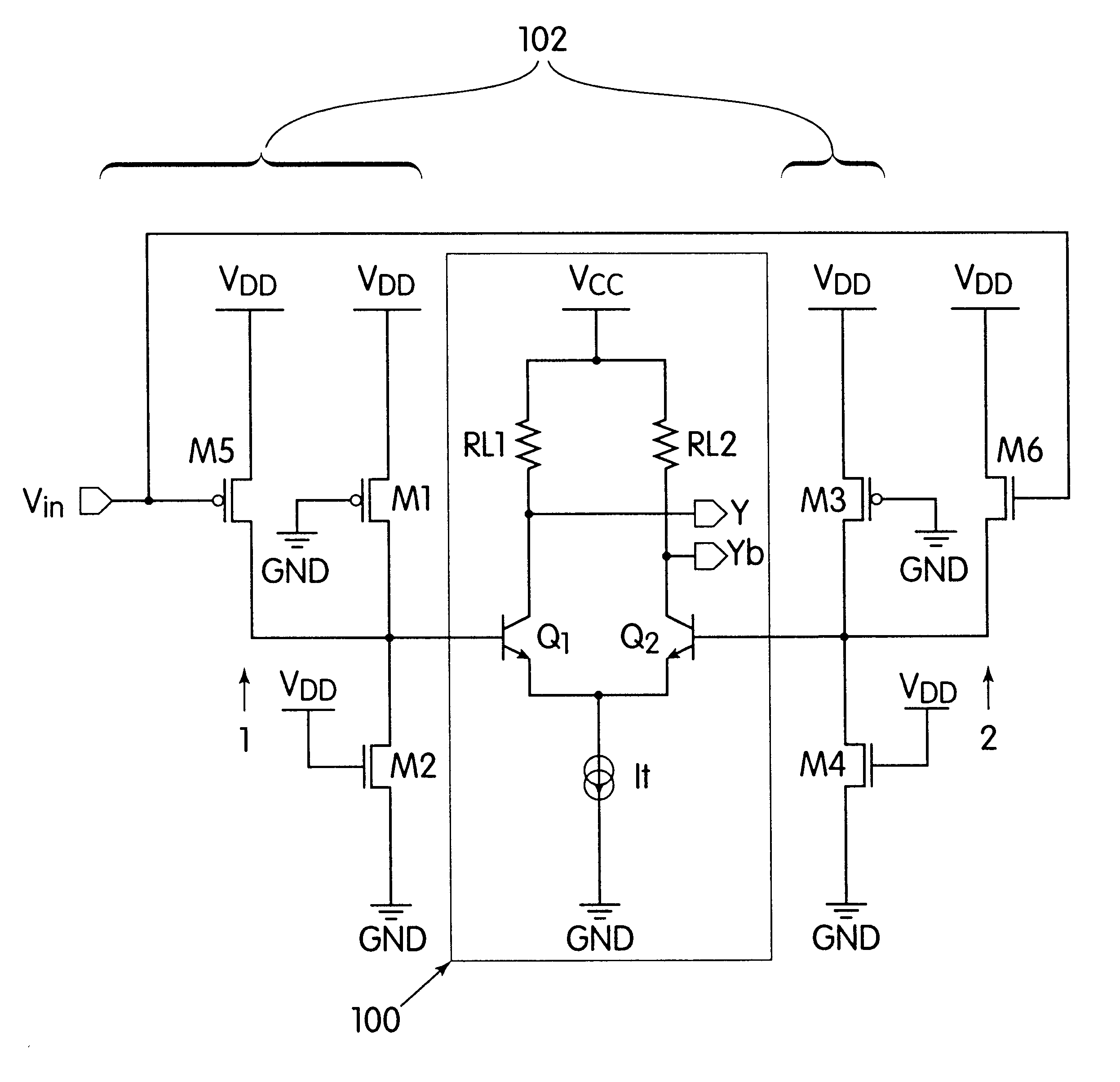
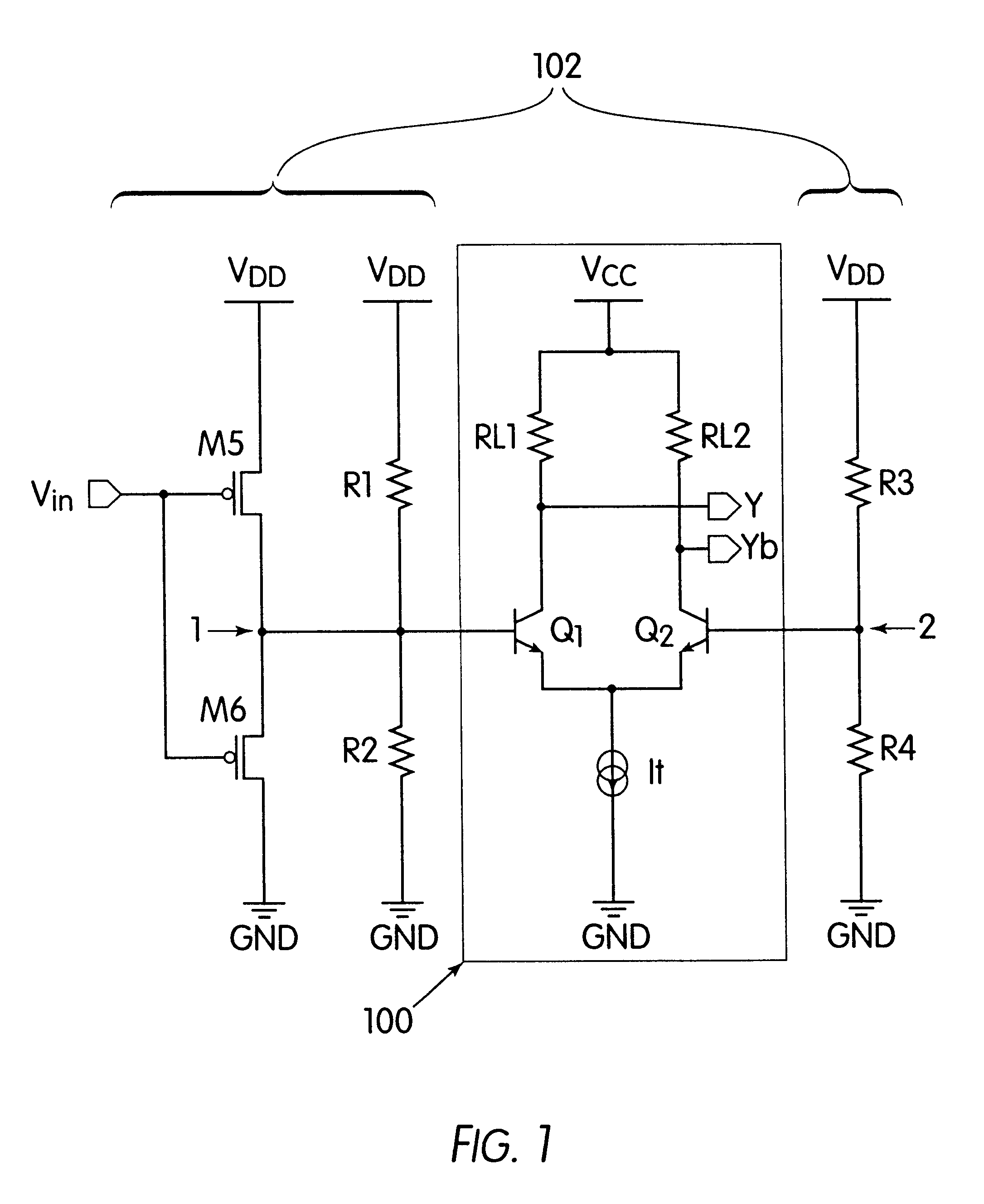
FIG. 1 shows an embodiment of the present invention where an interface circuit 102 provides a differential reduced-swing voltage signal to a circuit 100. Note the interface circuit 102 represents the circuit other than circuit 100 in all FIGs of the specification.

In FIG. 1, reference numeral 102 illustratively represents a CMOS (complementary metal oxide semiconductor) interface circuit. Reference numeral 100 illustratively represents a bipolar PECL (positive emitter coupled logic) circuit which needs a differential input with reduce...


PUM


Abstract

A circuit provides differential logic signals and includes a differential-input circuit having a first differential input and a second differential input. A first unit receives an input voltage signal and a supply voltage for providing a first voltage to the first differential input via a first node. A second unit receives the supply voltage for providing a second voltage to the second differential input via a second node. The differential-input circuit outputs a signal in accordance with the first and second voltages.

Description

BACKGROUND OF THE INVENTION1. Field of the InventionThe present invention relates to a circuit and more particularly to a differential-input circuit for providing differential logic signals.2. Description of the Related ArtDue to the increasing demand for high speed data transmission and RF (radio frequency) wireless communications, the differential-input circuit such as an ECL (emitter coupled logic) is widely used for providing differential logic signals because of its application in high speed operations. To implement the digital control of the high speed circuit, an interface circuit, such as a MOS (metal oxide semiconductor) circuit, is employed because it provides high density, low cost, and low power consumption. To fulfill the high speed operation, a differential ECL generally includes bipolar transistors which require a differential reduced-swing input voltage, e.g., a differential input of voltages with a swing less than a swing from ground voltage to supply voltage. Howev...

Claims


Application Information

Patent Timeline
Patent Type & Authority Patents(United States)
IPC IPC(8): H03K19/0175
CPCH03K19/017527
Inventor YANG, JUNGWOOK
Owner INT BUSINESS MASCH CORP
Why Eureka
Try Eureka